
digital thermometer schematics

The digital thermometer circuit operates by measuring the voltage drop across the 1N4148 diode, which varies with temperature due to its negative temperature coefficient. As the temperature increases, the voltage drop across the diode decreases, allowing for a direct correlation between the voltage reading and the temperature. The circuit typically includes a power supply, the diode sensor, a resistor to limit current through the diode, and a digital multimeter configured to read voltage levels.
The calibration process is crucial for accuracy. By placing the diode in a controlled environment (ice water), the user can establish a reference point at 0 °C. The adjustment of potentiometer P1 ensures that the digital multimeter is properly calibrated to read zero volts when the diode is at this reference temperature. This setup allows for precise temperature measurements across the specified range, making it suitable for various applications where monitoring temperature is essential.
For practical implementation, the circuit should be designed with attention to component ratings and tolerances to ensure reliable operation. The 1N4148 diode should be chosen for its fast switching capabilities and low forward voltage drop, making it ideal for temperature sensing applications. Additionally, the digital multimeter should be capable of resolving small voltage changes to accurately reflect the temperature variations detected by the diode. Proper insulation and protection of the diode from environmental factors may also be necessary to maintain measurement fidelity.This digital thermometer circuit diagram uses a common 1N4148 diode as the temperature sensor. The temperature coefficient of the diode, -2 mV / 0C is exploited for this application to create an accurate electronic thermometer. To display the measured temperature, a digital multimeter is used and so we can measure temperature values from -9.
990C u p to +99. 90C. To set the minimum level (00C), place the diode in a glass of water filled with crushed ice (check the temperature first with a normal thermometer) wait until the thermometer shows zero degrees centigrade. Set P1 so that the digital voltmeter will display 000 when the diode senses zero degree centigade. 🔗 External reference
Related Circuits
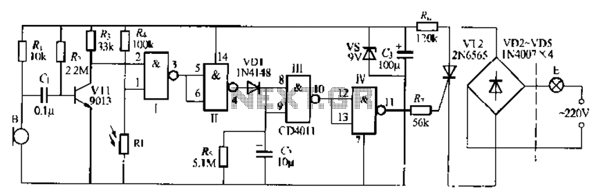
The CDI011 integrated circuit is designed for a sound and light-controlled stair delay switch circuit, which is relatively simple and effective. It utilizes a combination of NAND gates and differential input dynamics. The circuit has two input terminals; when...

This page describes a cheap and simple yet flexible HDMI to parallel 3.3V interface. This allows connecting most LCD frames to the BeagleBoard without any further interface required. It is used with some 7-inch 800x480 displays running Angstrom Linux...
The High Power Amplifier offers significant advantages, featuring a 5000W ultra-light, high-power audio amplifier without a switching-mode power supply. This device functions as a 2 x 2, 500W RMS stereo amplifier, designed to be super-lightweight and operates after the...
Analog-to-digital converters (ADCs), printed-circuit board (PCB), microcontroller or digital signal processor (DSP), total-harmonic-distortion (THD), signal-to-noise ratio (SNR). Analog-to-digital converters (ADCs) are essential components in modern electronic systems, enabling the conversion of analog signals into digital form for processing by microcontrollers...

This circuit is designed to provide long time delays using the integrated circuit Timer 555. It utilizes the NE555 to generate pulse frequencies, which are then divided by a 4017 decade counter to achieve the desired delay. The component...
Each step will result in a self-functional unit. By the end of this process, it will be possible to link the steps together into a powerful FM transmitter. This section will explain the main controlling unit for the FM...