
Digital Remote Thermometer

The digital remote thermometer features a remote sensor that effectively transmits temperature data over the mains supply, allowing for versatile applications in various environments. The operational temperature range of this device spans from 0.0 °C to 99.9 °C, making it suitable for monitoring a wide array of conditions.
The transmitter circuit is composed of several key components. Resistors R1 and R3, each rated at 100K ohms and 1/4 watt, are utilized to set the gain and stability of the circuit. Resistor R2, with a value of 47 ohms and also rated at 1/4 watt, is employed for current limiting purposes, ensuring that the circuit operates within safe parameters. The inclusion of R4, a 5K ohm trimmer resistor rated at 1/2 watt, allows for fine-tuning of the circuit, enabling adjustments to be made for optimal performance.
This design highlights the importance of selecting appropriate resistor values to ensure accurate temperature readings and reliable data transmission. The integration of the remote sensor with the mains supply for data transmission is a notable feature, facilitating ease of installation and reducing the need for additional wiring. Overall, this digital remote thermometer is a practical solution for temperature monitoring in both residential and industrial applications.Digital Remote Thermometer Remote sensor sends data via mains supply Temperature range: 00.0 to 99.9 C Transmitter circuit diagram: Transmitter parts: R1,R3=100K 1/4W ResistorsR2=47R 1/4W ResistorR4=5K 1/2W Trimm.. 🔗 External reference
Related Circuits
The circuit utilizes standard components, produces a good sine wave, and exhibits a degree of immunity to the specific operational amplifier it is designed around. However, it can be easily misunderstood, and oversimplifications regarding its operation may lead designers...
Electric single-girder cranes, also known as electric hoists, are commonly utilized in small factories for lifting and handling equipment. Typically, they are used in conjunction with drag line switching operation, which may not be very convenient. The circuit includes...
The successive approximation Analog to Digital Converter (ADC) is one of the most common types of ADC. It requires few components and is straightforward to operate. Additionally, it always takes the same amount of time to calculate the result....
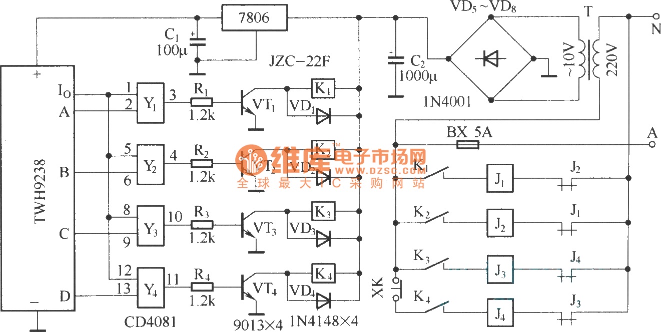
The circuit consists of two main components: (1) a power supply circuit featuring a transformer (T) that steps down AC 220V to 33V, followed by a full-wave rectifier, a filter, and a three-terminal regulator that outputs +24V. This circuit...
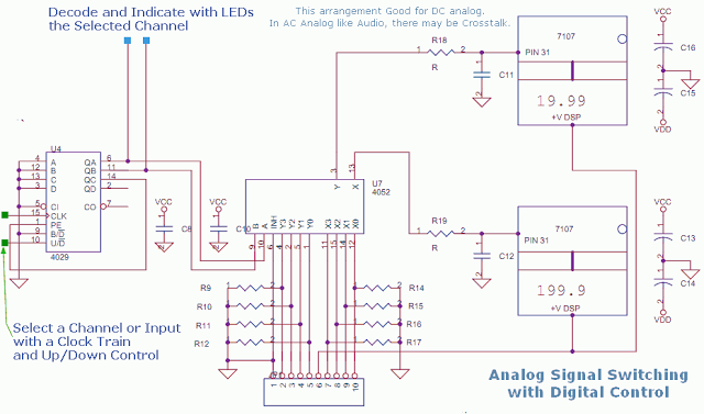
This circuit utilizes a 4052 as a DC Analog Multiplexer. The inputs to this multiplexer must originate from low-impedance output operational amplifiers (OpAmps). The resistors depicted are unnecessary once the signal conditioning OpAmps are connected. However, 100K resistors can...
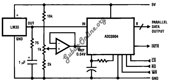
This is a design for a temperature-to-digital converter circuit that is controlled by the LM35 integrated circuit. The LM35 is a precision integrated circuit temperature sensor, whose output voltage is linearly proportional to the Celsius temperature. The circuit utilizes the...