
Temperature to Digital Converter Circuit

The circuit utilizes the LM35 temperature sensor to convert temperature readings into a digital format. The LM35 operates over a range of -55°C to +150°C, providing an output of 10 mV per degree Celsius. This characteristic allows for straightforward interfacing with analog-to-digital converters (ADCs) to facilitate digital signal processing.
In the schematic, the LM35 is connected to a microcontroller or an ADC via its output pin. The microcontroller can be programmed to read the voltage output from the LM35 and convert this analog voltage into a digital value through the ADC, which typically operates in a range of 0-5V or 0-3.3V. The reference voltage for the ADC must be set appropriately to ensure accurate temperature readings.
Additional components may include resistors for voltage division, capacitors for filtering noise, and possibly an operational amplifier to buffer the output signal from the LM35 if necessary. The design should also incorporate power supply decoupling capacitors close to the LM35 to stabilize its operation.
For applications requiring temperature monitoring, this circuit can be integrated into a larger system, such as a microcontroller-based temperature display or a data logging system. The output from the microcontroller can be utilized to trigger alarms or control heating systems based on the temperature readings. Overall, this design provides a reliable method for converting temperature measurements into a digital format suitable for various electronic applications.This is a design circuit for temperature to digital converter circuit that is based control by LM35 IC. This LM35 is precision integrated-circuit temperature sensors, whose output voltage is linearly proportional to the Celsius (Centigrade) temperatu ..
🔗 External reference
Related Circuits
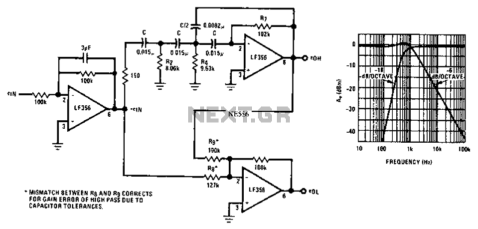
Asymmetric third-order Butterworth active crossover network circuit diagram. The asymmetric third-order Butterworth active crossover network is a sophisticated circuit designed to split an audio signal into two separate frequency bands, typically for use in multi-way speaker systems. This type of...
There is no substitute for sheer power—low-efficiency speakers, outdoor sound systems, or perhaps the full dynamic range of a high-power amplifier. Whatever the requirement, this super power module should meet the needs. The amplifier can be divided into three...
A circuit is being designed to operate based on car locks, which receive a negative pulse to activate a latched relay, powering the ACC line that connects to a startup/shutdown controller. The current circuit configuration presents a challenge; to...

The circuit demonstrates a method for powering CMOS integrated circuits (ICs) using RS-232C lines. The MAX680 is typically employed to generate a voltage equal to ±2 Vcc. This circuit operates in the opposite manner, accepting ±10.5 to ±12V from...
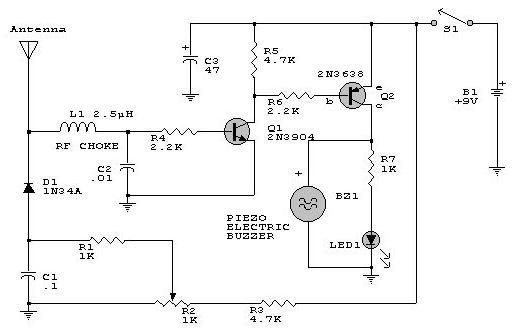
This electronic RF detector project is designed using common transistors and a few standard electronic components. The RF detector responds to RF signals below the standard broadcast band and well over 500 MHz, providing both visual and audible indications...
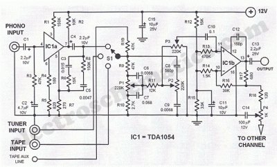
This Hi-Fi stereo preamplifier circuit is constructed using the TDA1054 integrated circuit (IC) from SGS. The TDA1054 is housed in a 16-pin DIL package and incorporates two separate preamplifier circuits. It is characterized by low noise and minimal issues...