
Digital scoreboard circuit

The digital scoreboard circuit operates by controlling a 7-segment display that utilizes a common anode configuration. In this setup, all the anodes of the individual segments are connected to a positive voltage supply, while the cathodes are connected to the control circuitry. Each segment of the display corresponds to a particular bit in a binary-coded decimal (BCD) representation of the numbers 0 through 9.
To facilitate the display of numbers, a binary to 7-segment decoder is typically employed. This decoder receives a 4-bit binary input representing the decimal digits and translates it into the corresponding output signals that illuminate the appropriate segments of the display. For instance, the digit '0' would activate segments a, b, c, d, e, and f, while segment g would remain off.
The circuit may include a microcontroller or a simple combinational logic circuit to generate the appropriate binary inputs based on user interaction or external signals. The microcontroller can be programmed to increment the displayed number based on button presses or timed intervals.
Power supply considerations are critical in this design. A regulated DC voltage source, typically 5V, is used to power the display and control circuitry. Current-limiting resistors are necessary to prevent excessive current from flowing through the segments, which could lead to damage. The value of these resistors is determined based on the forward voltage drop of the segments and the desired current for optimal brightness.
In summary, the digital scoreboard circuit is a straightforward yet effective design that allows for the clear display of numerical values using a common anode 7-segment display, driven by a decoder and controlled by either a microcontroller or logic circuitry. Proper power management and component selection are essential for ensuring reliable operation and longevity of the display.Digital scoreboard circuit functions to display values from 0 to 9 on the 7 segment display. 7 segments using a common type of anode 🔗 External reference
Related Circuits
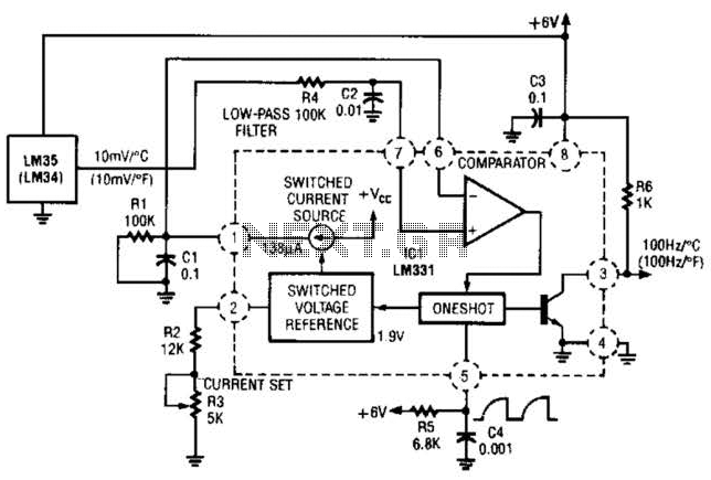
In this circuit, an LM34 or LM35 generates a frequency that is proportional to temperature. The reference current (138) is established through resistor R3. The output can be utilized to drive a display, frequency counter, or other indicating devices...

This is a wideband high-frequency amplifier circuit designed for a frequency range between 75-150 MHz. It utilizes a PNP transistor amplifier to enhance signal strength before it reaches the receiver of devices such as phones, FM radios, or amateur...
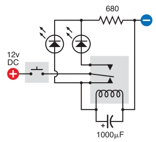
The intended result is for the relay to oscillate and the LEDs to flash when the button is pressed. However, when the button is pressed, the leftmost LED lights constantly, and nothing else happens. There is voltage across the...
When the tank is empty, the wires within it are open-circuited, causing the 180K resistor to pull the switch low, resulting in the switch being open and the LEDs being OFF. As water begins to fill the tank, the...
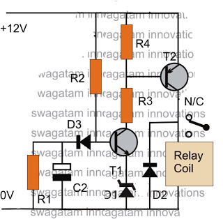
The post discusses a simple delay ON circuit that enables a connected load at the output to be activated with a predetermined delay after the power switch is turned ON. This circuit can be utilized in various applications that...
A battery-powered light control circuit is designed to delay the lighting of a small lamp during sudden power outages or nighttime situations when a blown fuse leaves a room in darkness. This circuit addresses the difficulty of locating matches...