
make this simple delay on timer circuit

An automatic voltage stabilizer rated at 1KVA exhibits a defect where it outputs a very high voltage for approximately 1.5 seconds upon being switched ON, causing frequent fusing of CFLs and bulbs before stabilizing to an acceptable voltage. The stabilizer comprises an auto-transformer and four 24V relays, each connected to a separate circuit that includes a 10K preset resistor, a BC547 transistor, a zener diode, a BDX53BFP NPN Darlington pair transistor IC, two capacitors (220uF/63V and 100uF/40V), four diodes, and additional resistors. These circuits are powered by a step-down transformer, and the outputs are taken across the corresponding 100uF/40V capacitor and fed to the respective relay.
To address the issue, it is suggested to investigate whether one of the relays is momentarily connecting the wrong contacts to the output or if one of the relays is taking longer to stabilize with the correct voltage after power ON. Given the presence of multiple relays, tracing the fault may be challenging. Implementing the delay ON timer circuit described earlier could effectively resolve this problem by ensuring that the output is activated only after a delay, allowing sufficient time for the internal relays to stabilize with the correct voltages across their output contacts.
The delay ON circuit operates effectively by utilizing a capacitor to create a time delay before activating the load. The capacitor charges through a resistor, creating a time constant that determines the delay duration. The variable resistor can be adjusted to set the desired delay period, making the circuit adaptable to various applications. The use of transistors as switches allows for efficient control of the relay, enabling the load to be powered only after the delay, thus preventing any premature voltage spikes from reaching the connected devices. This configuration is particularly beneficial in scenarios where sensitive electronic equipment is used, as it protects against potential damage caused by voltage fluctuations during startup.
In summary, the delay ON circuit provides a reliable solution for managing power supply issues in systems with multiple relays, ensuring that the connected load is activated only after the necessary stabilization period. This design enhances the longevity and reliability of both the stabilizer and the connected devices.The post explains a simple delay ON circuit which allows the connected load at the output to be switched ON with some predetermined delay after power switch ON. The explained circuit can be used for all applications which calls for an initial delay ON feature for the connected load after the mains power is switched ON.
The shown diagram is pretty straightforward yet provides the necessary actions very impressively, moreover the delay period is variable making the set up extremely useful for the proposed applications. Assuming the load which requires the delay ON action being connected across the relay contacts, when power is switched ON, the 12V DC passes via R2 but is unable to reach the base of T1 because initially, C2 acts as a short across ground.
Once C2 charges up to a level which develops a potential of 0. 3 to 0. 6V (+zener voltage) at the base of T1, T1 is instantly switched ON, toggling T2, and the relaysubsequently. finally the load gets switched ON too. I have a 1KVA automatic voltage stabilizer. It has one defect that when it is switched on, very high voltage is outputted for about 1. 5s (therefore cfls and bulb got fused frequently) after that the voltage becomes OK. I have opened the stabilizer it consist of an auto-transformer, 4 24V relay each relay connected to aseparatecircuit(each consisting of 10K preset, BC547, zener diode, BDX53BFP npn darlington pair transistor IC, 220uF/63v capacitor, 100uF/40V capacitor, 4 diodes and some resistors).
These circuits are powered by a step down transformer and output of these circuit are taken across corresponding 100uF/40V capacitor and fed to corresponding relay. What to do in order to tackle the problem. please help me. Hand drawn circuit diagram is attached. The problem in the above circuit might be due to two reasons: one of the relays is switching ON momentarily connecting the wrong contacts with the output, or one of the responsible relays is settling down with the correct voltages a little while after power switch ON.
Since there are more than one relay, tracing out the fault and correcting it can be a bit tedious. the circuit of a delay ON timer explained in the above article could be actually very effective for the discussed purpose. The above wiring would instantly take care of the issues as now the output would switch after some time during power witch ONs, allowing enough time for the internal relays to settle down with the correct voltages across their output contacts.
🔗 External reference
Related Circuits
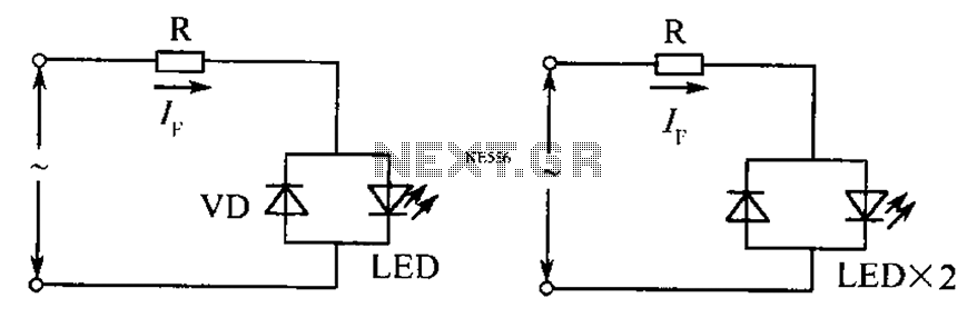
The circuit operates effectively even when the polarity of the voltage or the power supply is reversed. It functions with DC drives similar to AC drives, utilizing a current limiting resistor R. The value of this resistor is determined...
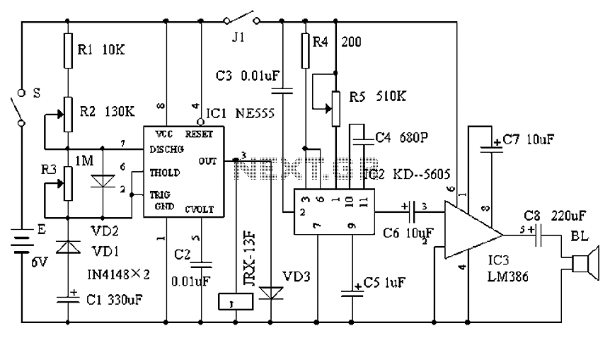
Cats are natural predators of rats, and the use of electronic devices to simulate meowing sounds as a repellent is an effective method. These electronic devices can produce meowing sounds at various frequencies and intervals, making them suitable for...
This is a simple and cost-effective inverter designed to power a small soldering iron (25W, 35W, etc.) when a mains supply is not available. The circuit utilizes eight transistors along with several resistors and capacitors. Transistors Q1 and Q2,...
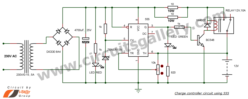
This is a simple DIY charge controller schematic created in response to a request from one of the readers on our Facebook page. The primary component of this automatic battery charger circuit is a 555 timer, which compares the...
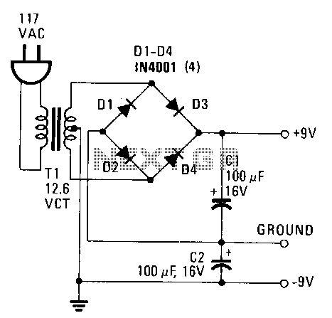
This power supply provides both +9 V and -9 V outputs to replace two 9-V batteries. The rectifier circuit consists of two separate full-wave rectifiers, each connected to the secondary winding of the transformer. The first full-wave rectifier, made...
This timer is designed for individuals seeking to achieve a tan while minimizing excessive exposure to sunlight. A rotary switch allows the user to set the timer based on six classified photo-types. A photoresistor adjusts the preset time value...