
digital sine wave synthesis
The described circuit effectively utilizes PWM for generating analog signals, leveraging the capabilities of low-cost microcontrollers. The integration of an RC filter allows for the smoothing of PWM outputs, facilitating the creation of desired voltage levels and waveforms. By employing a look-up table, the circuit can produce precise sine wave outputs, which are particularly advantageous in audio applications. The implementation of a rotary encoder for frequency adjustment provides a user-friendly interface, allowing for both coarse and fine adjustments to be made easily. The design also includes visual feedback via an LED, enhancing usability. The choice of components, such as the Freescale MC9S08QD4 microcontroller and the BOURNS PE12LS encoder, reflects a balance of performance and cost-effectiveness, making this circuit suitable for various applications that require analog signal generation from digital sources.For the most part we live in an analog world and when using a microcontroller, it is often necessary to be able to convert a digital value into its analog equivalent (or, for that matter, an analog value to a digital value but that`s not what this post is about). Many of the low end and low cost microcontrollers available today do not implemen t a built in hardware digital to analog converter (DAC). However, most do contain an 8 bit or 16 bit timer that is capable of producing Pulse Width Modulation (PWM). Pulse Width Modulation is primarily used to control power to a load such as a motor or a lamp by varying the pulse width (duty cycle) of a fixed frequency square wave.
The load responds to the average voltage that represents the duty cycle of the waveform. Increasing the pulse width will result in an increase in the average voltage level to the load along with a corresponding increase in the motors speed or the lamps intensity. However, Pulse Width Modulation, in conjunction with a simple resistor and capacitor (RC) filter, can also be used to generate specific DC voltage levels or various analog waveforms such as sine or triangle waves (also referred to as Direct Digital Synthesis or DDS).
As an example, to produce a DC voltage that is 50% of the MCU`s supply voltage, it is only necessary to output a waveform that has a 50% duty cycle and filter it with a simple RC filter. In a similar manner, to produce an output voltage that is either 25% or 75% of the supply voltage, the duty cycle is changed to either 25% or 75%.
It should be noted that the PWM frequency used should be as high as possible in order to keep the values of the RC components small. Accurate sine waves can be created by using Pulse Width Modulation, an RC filter and a look-up table with the correct sine wave values.
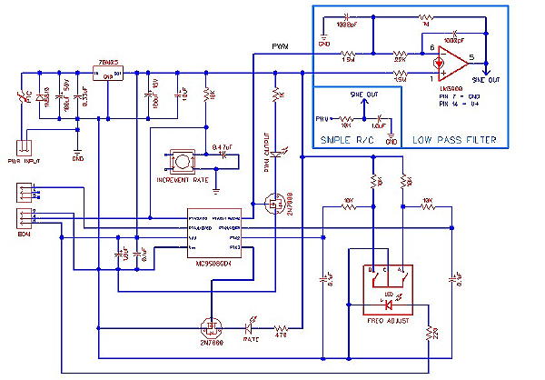
Low frequency sine waves are useful in electronic music applications such as adding tremolo or creating rotating sound effects. The circuit used for the sine wave generator is similar to the one used in the digital square wave generator (see an earlier post) with the exception of different firmware and the addition of a low pass filter.
The microcontroller (Freescale MC9S08QD4) circuit was designed to allow adjusting the frequency of the sine wave output. The frequency output can be adjusted from 141. 5 milliHerz (0. 1415 Hz) to 141. 5 Hz. A push button switch is used to adjust the rate (step) of frequency increase. A rotary encoder is used to adjust the frequency output. The encoder is a BOURNS PE12LS (2-bit quadrature output), with 24 pulses per rotation and also has an illuminated shaft.
The encoder is used in conjunction with the key board interrupt to increase or decrease the value of the delay time between changes in the timer value registers (TPMC0V i. e. the values in the look-up table). A longer delay time results in a lower frequency. The encoder increases or decreases the delay time in either 50 delay cycles per detent (COARSE ADJ) or 2 delay cycles per detent (FINE ADJ).
The two different delay increment values (coarse or fine) are selected using a single pushbutton in conjunction with another interrupt routine. A yellow LED indicates which increment value is selected (LED on = fine adjustment value). The sine wave frequency value is maintained when switching from coarse to fine adjustment. The slight drawback to this method is that there is some loss in resolution when setting a high frequency sine wave value due to the smaller ratio between the adjustment value and the delay value most noticeable when setting the higher frequencies.
Edge aligned PWM mode (eight bits used) uses the normal up counting mode of the timer counter. The duty cycle is determined by the value in the timer value register (TPMC0V) which is located in the look-up table. A value of 0 in the timer value register will result in a duty cycle of 0%. A value greater than the modulus (256) will result in a 🔗 External reference
Related Circuits
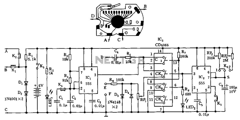
A circuit utilizing a standard digital quartz electronic watch, with its crystal soldered, forms a digital frequency meter as illustrated by the connected circuit. The test signal is applied to the E and F sides via components such as...
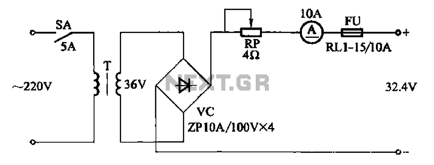
The adjustment potentiometer RP can modify the charging current. The adjustment potentiometer, designated as RP, serves a critical role in regulating the charging current within an electronic circuit. This component is typically a variable resistor that allows for fine-tuning of...
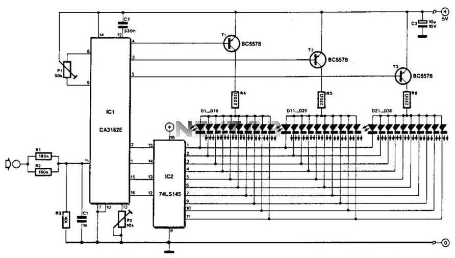
The voltage to be measured is digitized in an analog-to-digital (A/D) converter and then displayed in three decimal digits. The display consists of three groups of 10 LEDs. The meter can only be used for measuring direct voltages. The...
The circuit diagram for a multiple output digital camera power supply using the MAX1802 is illustrated below. The MAX1802 chip features two buck converters and three boost converters. It accepts an input voltage range of 2.5 to 11V and...
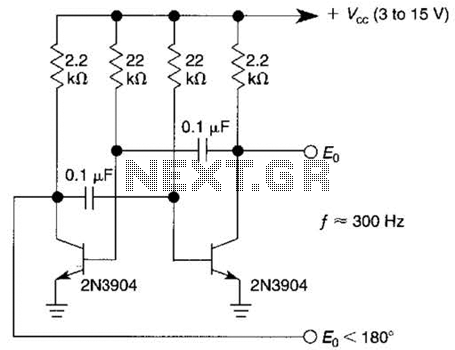
This free-running square-wave oscillator utilizes two NPN transistors. The output frequency is approximately 300 Hz with the specified component values. The circuit operates as a basic oscillator, generating a square wave output through the interaction of two NPN transistors. The...
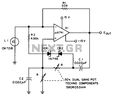
The Lamp LI stabilizes the loop gain at higher frequencies, while the limiting action of R2, CRI, and CR2 prevents clipping at low frequencies and increases the frequency adjustment range from approximately 3:1 to over 10:1. Additionally, waveform purity...
Warning: include(partials/cookie-banner.php): Failed to open stream: Permission denied in /var/www/html/nextgr/view-circuit.php on line 713
Warning: include(): Failed opening 'partials/cookie-banner.php' for inclusion (include_path='.:/usr/share/php') in /var/www/html/nextgr/view-circuit.php on line 713