
Digital Step-Km Counter

The digital step-kilometer counter is designed to accurately measure and display the distance traveled in meters. The core of the circuit typically consists of a microcontroller or a digital counter IC, which processes input from a step detection mechanism, such as a piezoelectric sensor or a simple mechanical switch activated by footfalls.
The resistors R1 and R3, both rated at 22K ohms, are used for biasing and setting thresholds within the circuit. They may be part of a voltage divider network that helps in conditioning the signal from the step detection mechanism before it is fed into the microcontroller. The power supply for the circuit can be sourced from a small battery, ensuring portability and ease of use.
The output display is likely a two-digit seven-segment LED or LCD display, which shows the distance in meters. The microcontroller processes the input signal and increments the displayed value based on the number of steps detected, converting this into a distance calculation based on a predetermined step length.
To enhance usability, the device may include additional features such as a reset button to clear the distance counter, and possibly a mode switch to toggle between different measurement units or settings. The compact design allows for easy carrying in a pocket, making it an ideal companion for fitness enthusiasts engaged in walking or jogging activities.
Overall, this digital step-kilometer counter combines simplicity with functionality, providing users with a reliable method to track their distance traveled during physical activities.Digital Step-Km Counter. Max. range: 9,950 meters with two digits. Slip it in pants` pocket for walking and jogging. Circuit diagram: Parts: R1,R3 22K 1/4W. 🔗 External reference
Related Circuits
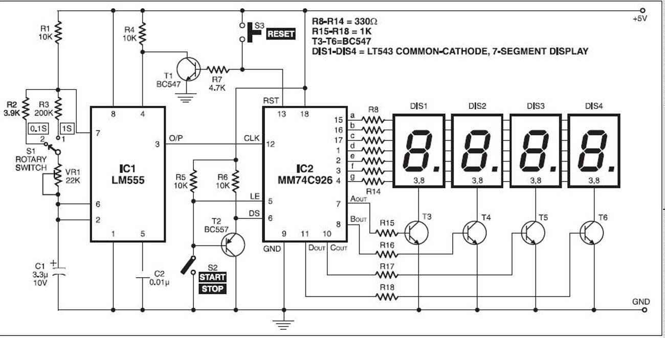
The stopwatch is constructed using a digital timer IC LM555 and an MM74C926 4-digit counter with a multiplexed 7-segment LED display. The MM74C926 features a 4-digit counter, an internal output latch, NPN output for controlling the common cathode source...
The function generator features two BNC outputs: one for the high speed [1 to 8 MHz] square signal (BNC1) and another for the DDS signal (BNC2). Offset and amplitude can be regulated by two potentiometers: offset in range of...
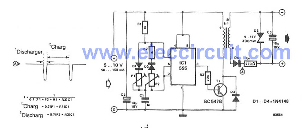
This circuit is a simple DC to DC converter designed for digital circuits. It operates with a supply voltage of 5V and provides an output voltage that steps up to a maximum of 10V-12V DC. The circuit utilizes an...
This experiment has two main objectives. First, it aims to familiarize participants with the characteristics of the Geiger-Müller (GM) tube, including its threshold, starting and operating voltages, GM plateau region, and plateau slope. The second objective is to utilize...
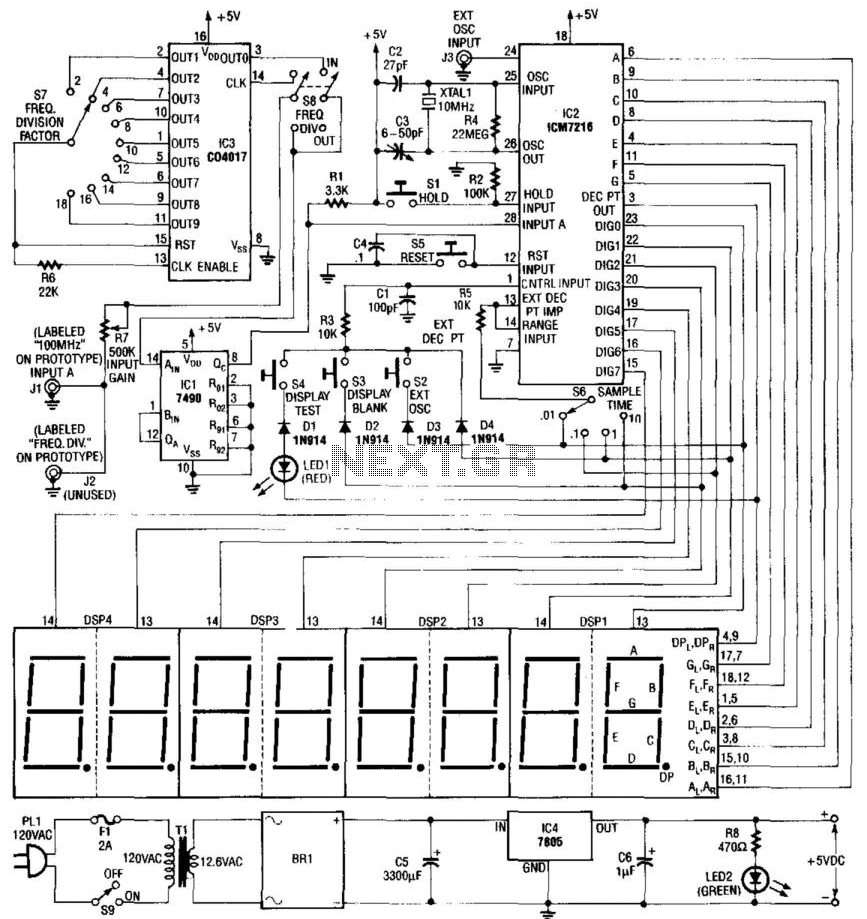
Built around an Intersil 7216 frequency counter IC, this counter has a basic range of 10 MHz, a 100-MHz prescaler, and an extra frequency divider (IC3). This divider reduces the frequency by an additional factor, as indicated on S7...
This Project Digital Calendar using Microcontroller is an advanced digital calendar, which displays the Date, Day, Month over the LED display. It has an 8 bit Microcontroller which runs on the Program embedded on its ROM. Separate LEDs are...