
Simple DC Converter For Digital Circuit by IC 555

The circuit operates by employing the 555 timer in an astable mode configuration, which generates a pulse-width modulation (PWM) signal. This PWM signal is then used to control a switching element, typically a transistor or a MOSFET, that regulates the energy transferred to an inductor. The inductor stores energy when the switching element is turned on and releases it to the output when the switching element is off, effectively increasing the voltage.
The key components of this circuit include the 555 timer IC, resistors, capacitors, an inductor, and a diode. The values of the resistors and capacitors connected to the 555 timer determine the frequency and duty cycle of the PWM signal. Selecting appropriate values for these components is crucial for achieving the desired output voltage.
The inductor is chosen based on the required output current and voltage ripple specifications. A Schottky diode is often used for its fast recovery time, which minimizes losses during the energy transfer phase. The output capacitor smooths the voltage, reducing ripple and providing a stable output voltage.
This simple DC to DC converter is suitable for powering low-power digital circuits that require a higher voltage than the available supply voltage. It is essential to ensure that all components are rated for the voltages and currents they will encounter during operation to prevent damage and ensure reliability. Proper layout and grounding techniques should also be employed to minimize electromagnetic interference (EMI) and ensure stable operation.This circuit Simple DC to DC Converter For Digital Circuit. It use Volt supply 5V Only, To Output Step up Volt 10V-12V DC max. I use IC 555 ( hot ic Timer) for.. 🔗 External reference
Related Circuits
The thermocouple cold junction compensation circuit and the MAX6675 converter circuit diagram form a temperature measuring system. The system utilizes a K-type thermocouple connected to the T terminals of the MAX6675, with the cold junction grounded. An 8051 microcontroller...
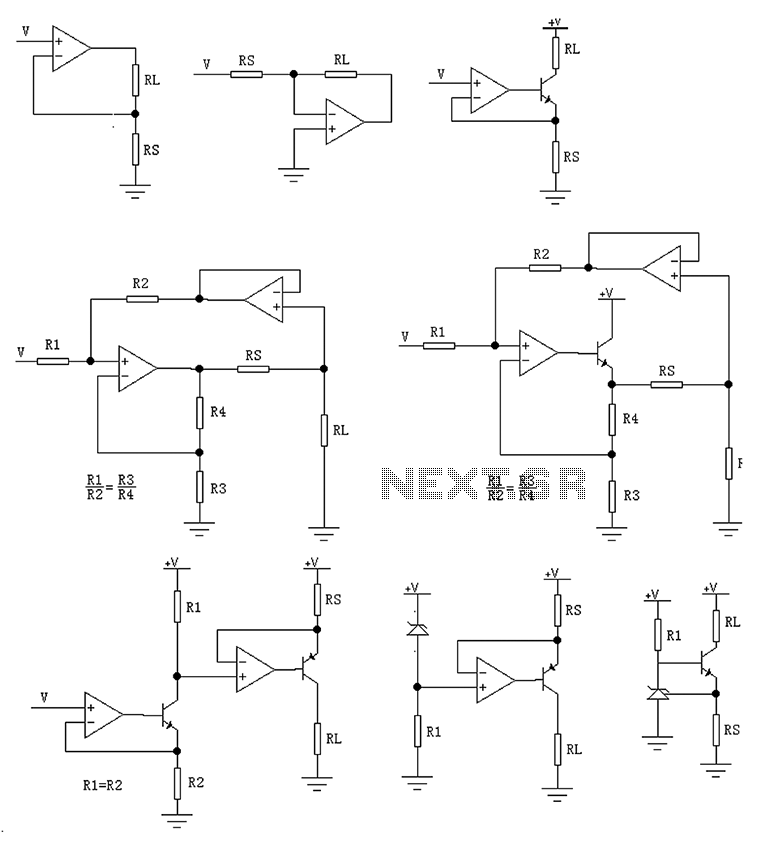
The circuit is designed to provide several constant current outputs to the load resistor RL. The first RL is floating and is rarely utilized. The second RL serves as a virtual ground and is not commonly used either. The...
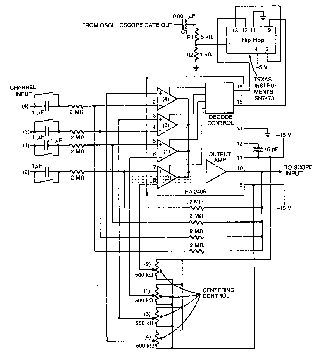
The monolithic quad operational amplifier offers a cost-effective solution for enhancing the display capabilities of a standard oscilloscope. Binary inputs control the integrated circuit operational amplifier, while a dual flip-flop divides the oscilloscope's gate output to generate channel selection...

The circuit demonstrates a method for powering CMOS integrated circuits (ICs) using RS-232C lines. The MAX680 is typically employed to generate a voltage equal to ±2 Vcc. This circuit operates in the opposite manner, accepting ±10.5 to ±12V from...

This light sensor switch circuit enables the automatic activation of a lamp when ambient light levels decrease, such as during nightfall. The duration for which the lamp remains on can be adjusted using potentiometer P1, with a range of...
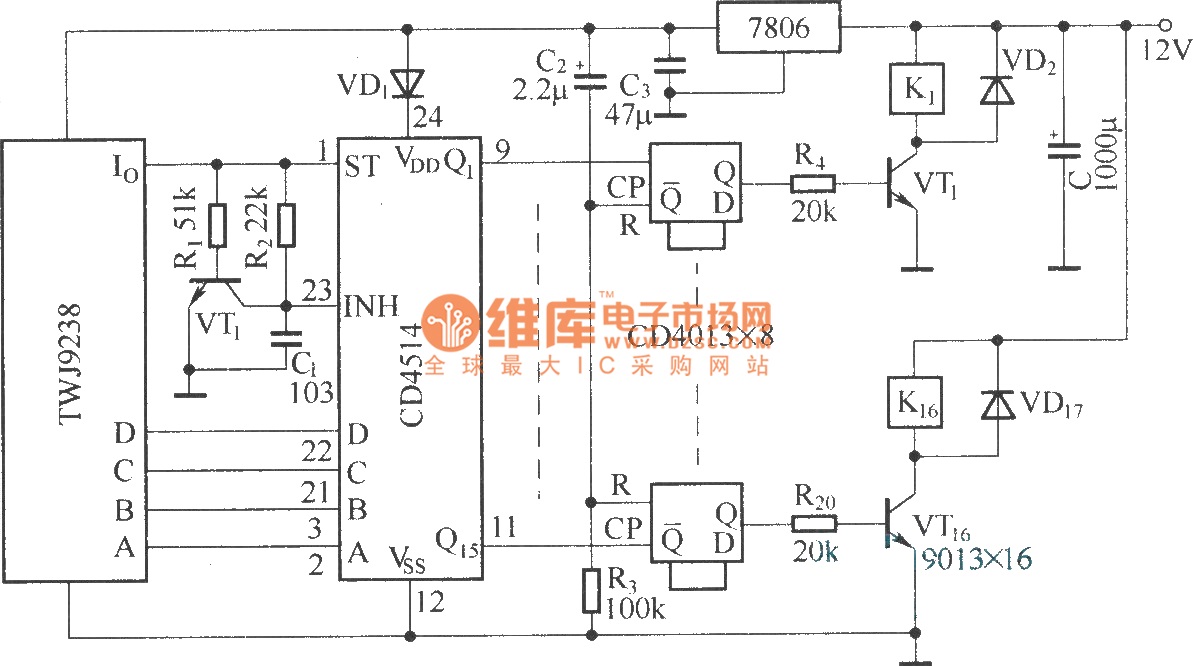
The Sixteenth Street control circuit consists of a secondary decoding output control circuit. Each output terminal of the sixteen decoding is connected to a bistable circuit made up of dual D flip-flops (CD4013). A DC relay is connected to...