
Digital Step-Km Counter

The circuit operates based on a simple yet effective mechanism for distance measurement while walking. The integration of a mercury switch allows for the detection of movement, translating physical steps into electrical signals. The choice of a monostable multivibrator configuration (IC1A and IC1B) is crucial in ensuring that any mechanical bouncing from the mercury switch does not lead to erroneous counts. This is particularly important in mobile applications where vibrations can occur.
The use of a pulse divider (IC2) to manage the count further enhances the accuracy of the measurement by translating the number of detected steps into a user-friendly display format. The division by 64 means that for every 64 detected pulses, one unit of distance (50 meters) is indicated on the display, thereby simplifying the user's understanding of the distance covered.
The design also incorporates energy-saving features, such as the display activation upon request, which is essential for portable devices. The dual pushbutton reset mechanism adds a layer of protection against accidental resets, ensuring that the user’s data remains intact during operation.
The audio feedback via the piezo sounder (driven by Q1) provides an auditory cue for each counted unit, enhancing user interaction with the device. The option to disable this feature (via SW2) allows for customization based on user preference, making the device versatile for different environments.
In summary, this circuit represents a practical solution for tracking walking distances, with careful consideration given to user interface, power management, and accuracy of measurement. The overall design reflects a well-thought-out approach to creating a functional and user-friendly electronic device for fitness tracking.This circuit measures the distance covered during a walk. Hardware is located in a small box slipped in pants` pocket and the display is conceived in the following manner: the leftmost display D2 (the most significant digit) shows 0 to 9 Km. and its dot is always on to separate Km. from hm. The rightmost display D1 (the least significant digit) sh ows hundreds meters and its dot lights after every 50 meters of walking. A beeper (excludable), signals each count unit, which occurs every two steps. A normal step is calculated to span approx. 78 centimeters, thus the LED signaling 50 meters lights after 64 steps or 32 mercury switch`s operations, the display indicates 100 meters after 128 steps and so on. For low battery consumption the display lights only on request, pushing P2. Accidental reset of the counters is avoided because to reset the circuit both pushbuttons must be operated together.
Obviously this is not a precision meter, but its approximation`s degree was found good for this kind of device. In any case, the most critical thing to do is placement and sloping degree of the mercury switch inside the box.
IC1A & IC1B form a monostable multivibrator providing some degree of freedom from excessive bouncing of the mercury switch. Therefore a clean square pulse enters IC2 that divide by 64. Q2 lights the dot of D1 every 32 pulses counted by IC2. IC3 & IC4 divide by 10 each and drive the displays. P1 resets the counters and P2 enables the displays. IC1C generates an audio frequency square wave that is enabled for a short time at each monostable count.
Q1 drives the piezo sounder and SW2 let you disable the beep. * This circuit is primarily intended for walking purposes. For jogging, further great care must be used with mercury switch placement to avoid undesired counts. 🔗 External reference
Related Circuits
The reason for this project was to facilitate a quick installation for a local friend 10 km away, enabling the start of real-life testing to identify and resolve bugs and problems before releasing it to other users. The software...
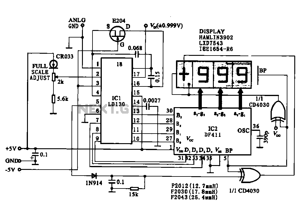
This circuit illustrates a display driving system for a digital voltmeter. The liquid crystal display (LCD) does not emit light by itself; it relies on external incident light for visibility. The integrated circuit (IC) LD130 serves as an input...
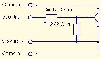
This is a straightforward guide to constructing a digital switch for a camera, enabling photo capture through microcontrollers. Required components include: 1. A digital switch for a camera can be implemented using a microcontroller, such as an Arduino or...
This is a simple frequency counter based on the microcontroller PIC16F84. Its maximum operating frequency is approximately 30 MHz, with a resolution of 10 Hz and low current consumption of 15 mA. The assembly process is straightforward. The device...
This PIC software integrates frequency counter and frequency locking functions. By incorporating a couple of transistors and an operational amplifier (TL082), it is feasible to stabilize the LC oscillator frequency. The frequency reference is established from the measured frequency...

This page describes a cheap and simple yet flexible HDMI to parallel 3.3V interface. This allows connecting most LCD frames to the BeagleBoard without any further interface required. It is used with some 7-inch 800x480 displays running Angstrom Linux...