
DVI to PAR digital video interface with LCD

The dvi2par also includes an optional I2C EEPROM, allowing use on hosts other than the BeagleBoard that support DDC/EDID configuration. However, this part has only been verified to work on a standard Linux desktop PC. To use it, an EDID description for the display needs to be built using the Phoenix EDID designer 1.3. The output must be programmed into the dvi2par DDC EEPROM, with jumper JP1 set to enable writing. The I2C port of the HDMI connector should be connected to Linux-controlled I2C hardware. The remaining parts have been purchased in Germany from Reichelt and Conrad.
Part list:
- X1: HDMI connector
- IC1: 3.3V regulator (LM2937 ET3.3)
- IC2: DDC EEPROM (ST 24C01 MN)
- IC7: TFP101A
- C2, C3: Capacitor 10uF/16V (SMD TAN.10/16)
- C1, C4-C7: Capacitor 100nF (X7R-G0805 100N)
- RN1-RN7: Resistor array 4*22R SMD (BCN16 22)
- R1, R3: Resistor 4.7k (SMD 0805 4.70K)
- R2: Resistor 100R (SMD 0805 100)
- R4, R5: Resistor 47k (SMD 0805 47.0K)
- D1: Diode 1N 4001 (SMD 1N 4001)
- SV1-SV4, JP1-JP2: Pinheader 1x36 (SL 1X36G 2.54)
- X2: Power connector (AKL 101-03)
This schematic provides a compact, efficient solution for interfacing HDMI signals with parallel LCD technology, addressing a common challenge in embedded systems development. The integration of the TFP101A chip simplifies the process by directly converting HDMI signals to the required voltage levels, while the optional EEPROM support enhances compatibility with various display configurations.This page describes a cheap and simple yet flexible HDMI to parallel 3.3v interface. This allows to connect most LCDs frames to the beagleboard without any further interface required. I am using this myself with some 7inch 800x480 displays which i am using to run Angstrom Linux as well as the maemo on beagleboard project. I have used these lately for some work on Meego. The hardware is rather simple and doesn't consist of much more than the TFP101A panel link receiver from TI.
This chip directly outputs 3.3V signals. The dvi2par routes these signals though 22R resistor arrays to reduce reflections. The resulting signals can be fed directly into a LCD screen as depicted below. From the day i received my beagleboard rev. B7 i was missing an easy way to use the digital video interface with a small LCD screen. Many people seem to have the same problem and often end up with big and expensive adaptors. Further indication that this is a common problem comes from the fact that the latest incarnation of the beagleboard includes a way to directly interface to the OMAPs parallel video interface. Unfortunatately this only provides 1.8v signals and still needs a converter to interface to the 3.3v signals most raw LCD use.
The main components is the TFP101A. I got mine as a free sample from TI. Also visible in this picture is the fact that only the upper 6 of the 8 color bits available on the dvi2par are being used. It's important to make sure that the upper bits are being used if the display supports less than 24 bit color depth.
Also visible in the image is the fact that a tiny wire goes from pin 8 of the TFP101A to some other parts on the board is mounted on. Pin 8 carries the SCDT signal which indicates that a valid signal has been detected in the input. In this example the signal is routed to the backlight inverter and makes sure that the backlight is only switched on if a valid HDMI signal is being received.
EDID/DDC support The dvi2par also includes an optional i2c eeprom which is meant to allow to use the dvi2par on hosts other than the beagleboard which support to use a displays ddc/edid configuration. However, this part has only been verified to be operational and to be usable on a standard linux desktop PC.
But since this part is not necessary on a beagleboard, it isn't tested to all detail. In order to use it, you need to build an EDID description for your particular display using e.g. the Phoenix EDID designer 1.3 (A windows software which runs fine in wine). The output of this editor needs then to be programmed into the dvi2par ddc eeprom. The jumper JP1 has to be set to enable writing the eeprom. The i2c port of the hdmi connector then needs to be connected to some linux controlled i2c hardware like e.g. my i2c-tiny-usb. Below is an image of my i2c-tiny-usb based adptor used to write the ddc eeprom on the dvi2par. All remaining parts have been bought in germany from Reichelt and Conrad. The part numbers are: Part Qty Name Reichelt Part No. Conrad Part No. X1 1 HDMI connector 530335-62 IC1 1 3.3V regulator LM2937 ET3,3 IC2 1 DDC eeprom ST 24C01 MN IC7 1 TFP101A C2,C3 2 Capacitor 10uF/16V SMD TAN.10/16 C1,C4-C7 5 Capacitor 100nF X7R-G0805 100N RN1-RN7 7 Resistor array 4*22R SMD BCN16 22 R1,R3 2 Resistor 4k7 SMD 0805 4,70K R2 1 Resistor 100R SMD 0805 100 R4,R5 2 Resistor 47k SMD 0805 47,0K D1 1 Diode 1N 4001 SMD 1N 4001 SV1-SV4,JP1-JP2 1 Pinheader 1x36 SL 1X36G 2,54 X2 1 Power connector AKL 101-03
🔗 External reference
Related Circuits
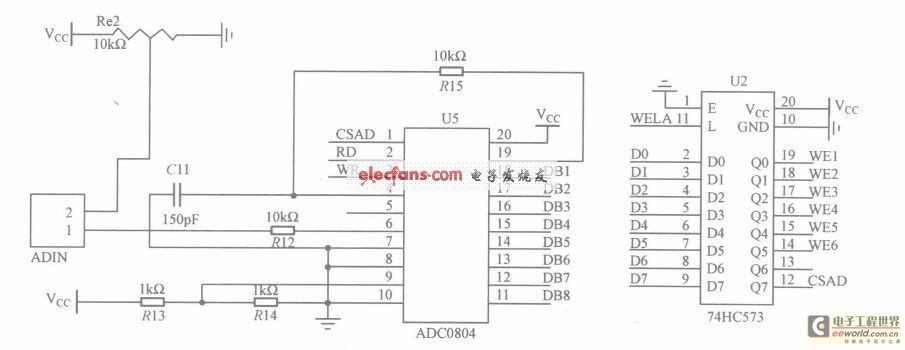
The circuit utilizes the ADC0804, which is configured for left-handed operation, alongside the 74HC573 latch, which is configured for right-handed operation. The latch is connected to a microcontroller, but they are not drawn in the same schematic. The CSAD...
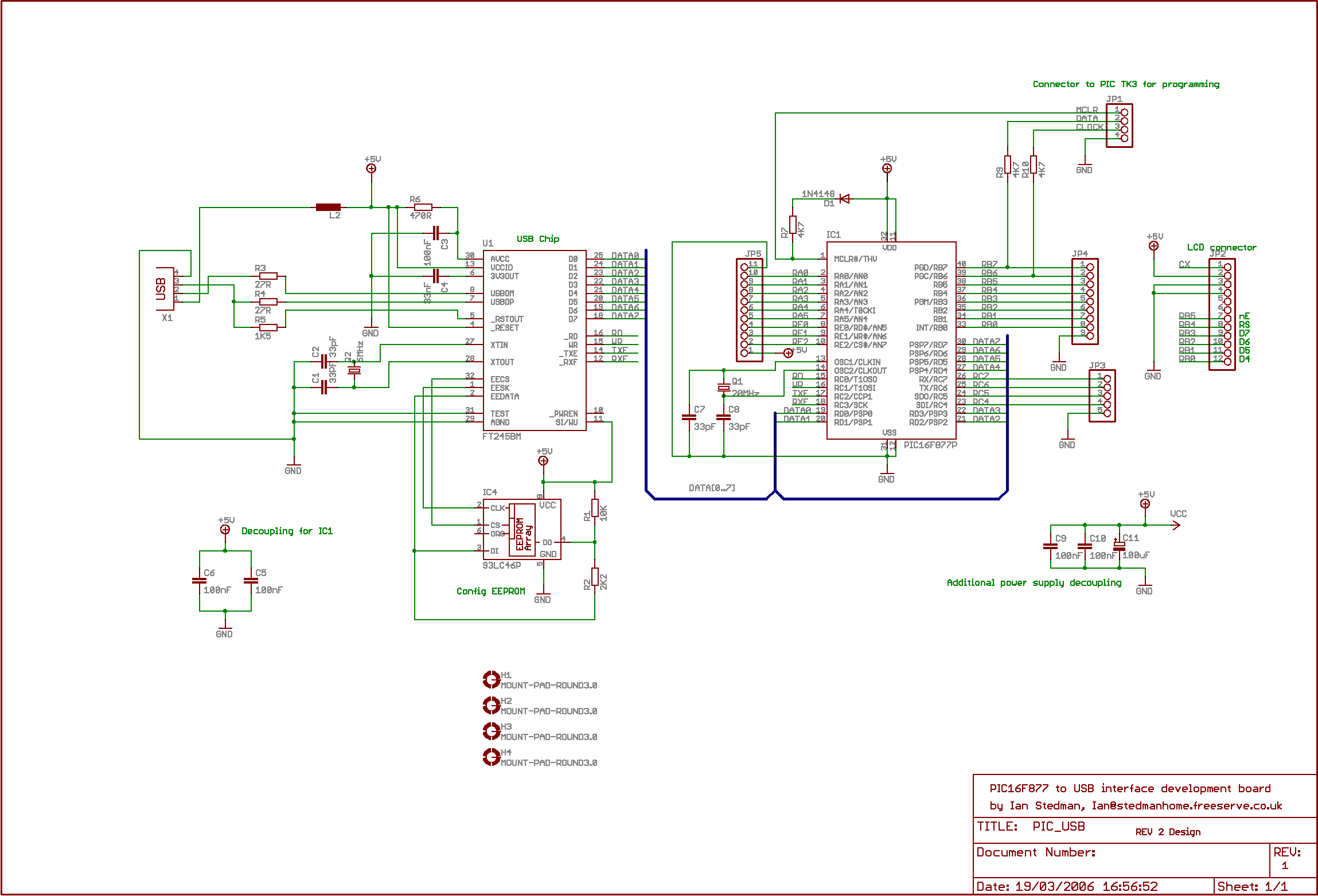
The second program sends "Hello world" to the PC. By default, the board utilizes the Virtual COM Port (VCP) driver, allowing output to be viewed using Hyperterminal or similar software; PuTTY is recommended. The setup is straightforward: upon connecting...
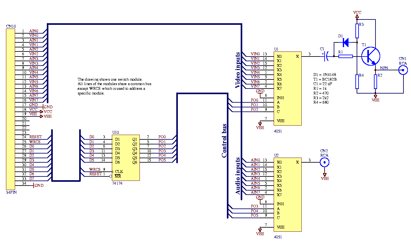
Each audio/video output can be switched to any of the eight inputs separately. One module drives one audio/video output and has a 34-pin connector to plug into the system interface. Video operational amplifiers (OPAs) can be used on the...
This circuit provides a visual 9 second delay using a 7 segment digital readout LED. When the switch is closed, the CD4010 up/down counter is preset to 9 and the 555 timer is disabled with the output held high....
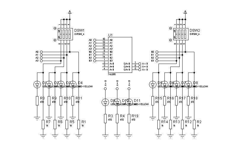
In designing a logic circuit, it is often necessary to compare the values of two digital data inputs. Creating a custom magnitude comparator can lead to increased use of logic integrated circuits (ICs), as well as greater time and...
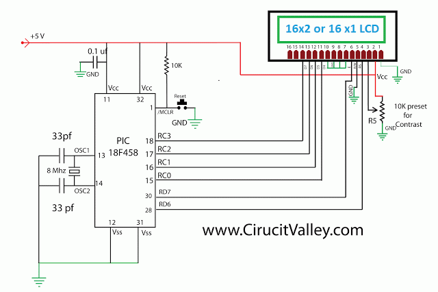
An alphanumeric low-cost LCD display is essential for many small and large projects to display various types of information. The Hitachi HD44780 chipset-based 16x2 character LCD is very affordable and easily available in the local market. This project covers...