
digital voltmeter circuit

The digital voltmeter circuit utilizing the ICL7107 is designed to provide accurate voltage measurements across a specified range. The ICL7107 is a versatile component that integrates several functionalities, including an internal voltage reference that stabilizes the measurement process, ensuring consistent readings. The high isolation analog switches allow for safe and effective switching between different measurement points without introducing significant interference or noise into the circuit.
The sequential control logic within the ICL7107 manages the operation of the A/D conversion process, ensuring that the analog signal from the probes is accurately converted into a digital format for display. The use of LED displays makes it user-friendly, providing clear and readable voltage readings.
To enhance performance, the recommendation for a dedicated PCB design is crucial. A well-designed PCB minimizes the effects of external noise and voltage drift, which can significantly affect measurement accuracy. Proper layout techniques, such as maintaining short trace lengths for high-frequency signals and ensuring adequate grounding, are essential for achieving optimal performance.
The connection of probes PLG1 and PLG2 to the circuit under test allows for direct measurement of the voltage difference. The selector switch (S2) provides flexibility by enabling the user to choose the appropriate voltage range, which is critical for accurate readings, especially when measuring voltages that may vary widely.
Calibration of the voltmeter is an essential step to ensure measurement accuracy. The potentiometer (P1) allows for fine adjustments to the displayed voltage, ensuring that it matches the known voltage source. This calibration process may require the use of a reference voltmeter, which serves as a standard against which the digital voltmeter can be calibrated.
Overall, this digital voltmeter circuit design is not only functional but also adaptable for various applications, making it a valuable tool for electrical measurements in both laboratory and field settings.This is a design circuit for digital voltmeter circuit. The integrated circuit ICL7107 is a 3-1/2 digit LED A/D convertor. It contains an internal voltage reference, high isolation analog switches, sequential control logic, and the display drivers. The auto-zero adjustment mechanism ensures zero reading for 0 volts input. The circuit is classic de sign and you can be sure that it will work fine. However, for better result, it is recommended to design a proper PCB for minimum voltage drift and noise. This is the figure of the circuit; Connect the positive and negative probes PLG1 and PLG2 to two points of the electric circuit you would like to know their electric potential difference or simply voltage.
You have to set the selector switch S2 to proper voltage range you expect those two points would have. To calibrate the volt-meter, use the potentiometer P1. Adjust it to read correct voltage on the display by connecting probes to a known voltage source. You may need to use another calibrated volt-meter in this case. 🔗 External reference
Related Circuits
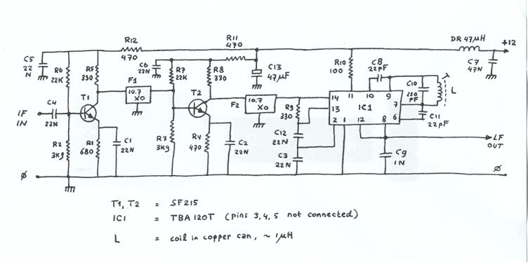
Two conventional amplifier stages built with SF215 transistors are linked by ceramic 10.7MHz IF filters, and followed by an FM demodulator built with a TBA120T i.c. Straight from the databook. Output goes via a 100k log potmeter (not shown)...
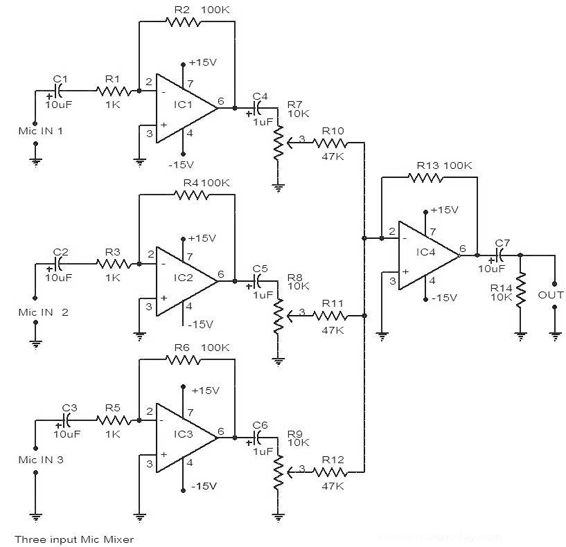
This is a circuit diagram of a 741 IC-based three-input microphone mixer circuit. A total of four 741 ICs are utilized, with IC1, IC2, and IC3 serving specific functions within the design. The circuit utilizes four operational amplifiers from the...
The following circuit illustrates a fully linear diode sensor circuit diagram. This circuit is based on the A748 integrated circuit (IC). Features include the use of an operational amplifier (op-amp). The fully linear diode sensor circuit utilizes the A748 IC...
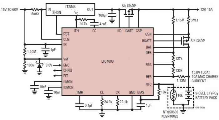
The LTC4000 high voltage controller, developed by Linear Technology, can be utilized to create a straightforward high current LiFePO4 battery charger. This charger delivers a fixed output voltage of 12 volts with a maximum output current of 15 A....
The following diagram is for the main circuit of the motor driver. A testing version is shown near the end of this page. It is laid out differently and shows the SN7474 in logic block form and LEDs are...
This circuit is a Digital Radar Speedometer that measures the speed of moving objects, particularly vehicles such as cars. The speed is displayed in kilometers per hour (KPH) and features a three-digit display. The radar operates using laser reflection...