
Fully Linear Diode SensorCircuit Based On The A748 IC

The fully linear diode sensor circuit utilizes the A748 IC to achieve precise measurements in various applications. The A748 is a high-performance op-amp known for its low offset voltage and high gain bandwidth product, which makes it suitable for sensor applications requiring linearity and accuracy.
In this circuit, the operational amplifier is configured in a feedback loop to maintain linearity across a specified range of input signals. The diode acts as the sensing element, converting physical phenomena—such as temperature, light intensity, or pressure—into an electrical signal. The output of the diode is fed into the op-amp, which amplifies the signal while minimizing distortion.
The circuit typically includes additional components such as resistors and capacitors to set the gain of the op-amp and filter out noise, ensuring that the output remains stable and reliable. The configuration may also incorporate a reference voltage to enhance the linearity of the response.
This sensor circuit can be applied in various fields, including industrial automation, environmental monitoring, and consumer electronics, where accurate sensing and measurement are critical. The design emphasizes simplicity and efficiency, allowing for easy integration into broader electronic systems.The following circuit shows about Fully Linear Diode Sensor Circuit Diagram. This circuit based on the A748 IC. Features: opamp as .. 🔗 External reference
Related Circuits
Atmel Flash devices are well-suited for development due to their ease and speed of reprogramming. They provide ample code space for applications, especially for projects involving the 89Cxx series with the C programming language. Atmel offers a wide selection...
This is a 7-segment counter circuit based on the IC 74LS90 TTL. It can be utilized in conjunction with various circuits where a counter enhances visual appeal. The circuit accepts any TTL-compatible logic signal and can be easily expanded....
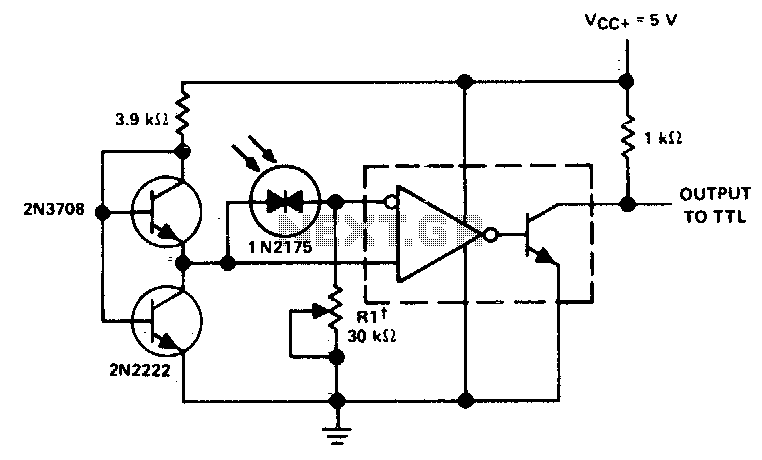
Rl sets the comparison level. At comparison, the photodiode has less than 5 mV across it, decreasing dark current by an order of magnitude. More: IC = LM 111/211/311. In this circuit description, the resistor Rl plays a crucial role...
This article outlines various audiophile projects, including the DDDAC 2000, and discusses components such as the 1N4001 diode. The content is straightforward and informative, providing insights into these projects. For instance, readers can find and purchase the 1N4001 diode...

This circuit is designed for sound detection and generates an output signal when sound is detected. This output can trigger another circuit that activates an alarm, making it suitable for security applications. The circuit employs a condenser microphone to...

The circuit design is relatively straightforward. It features a Voltage Controlled Oscillator (VCO) utilizing the ICL8038 along with supplementary components, a sine and triangle output stage using the LT1210, and a CMOS-compatible output stage driven by the MOSFET driver...