
Audio-rf signal tracer probe

The signal tracer is designed to facilitate the diagnosis and alignment of radio frequency (RF) circuits, particularly in receivers and low-power transmitters. The device operates by switching to RF mode, allowing it to detect modulation on incoming signals through a diode. The diode acts as a rectifier, converting the RF signal into a form that can be amplified. The subsequent amplification is performed by a Field Effect Transistor (FET), which enhances the signal strength for easier analysis.
The use of a twin-core shielded lead is critical in this setup. It serves a dual purpose: it connects the probe to an external amplifier, ensuring that the signal can be processed further, and it provides a power supply of 6 volts to the circuit. This power supply is essential for the operation of the FET and the overall functionality of the signal tracer.
The circuit design should include appropriate biasing for the FET to ensure optimal performance. Additionally, the diode should be selected based on its frequency response to ensure it can effectively detect the modulation present in the RF signals being tested. The shielding of the lead is also important to prevent interference from external electromagnetic fields, which could distort the signals being traced.
Overall, this economical signal tracer represents a valuable tool for technicians and engineers working in the field of electronics, enabling efficient troubleshooting and alignment of RF systems. Proper implementation of the circuit components and connections will enhance the reliability and accuracy of the device in various applications.This economical signal tracer is useful for servicing and alignment work in receivers and low power transmitters. When switched to RF, the modulation on any signal is detected by the diode and amplified by the FET A twin-core shielded lead can be used to connect the probe to an amplifier and to feed 6 volts to it.
Related Circuits
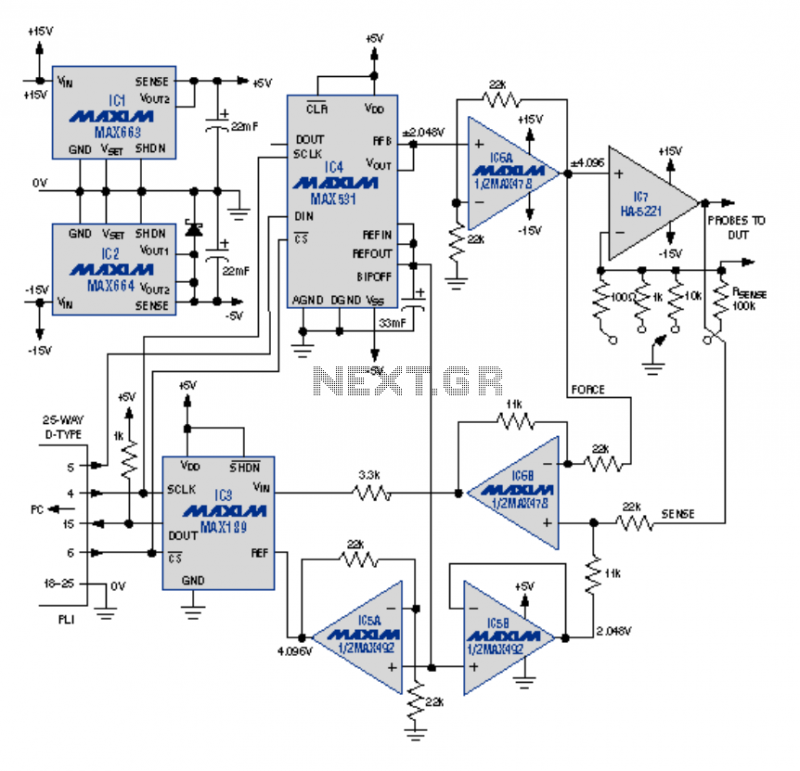
This article describes an I-V curve tracer circuit that uses a computer for display and control. The circuit is controlled via the PC parallel port. Software is provided, written in BASIC, to control the measurement and display the results...
Unlike conventional small-signal methods, employing large-signal, time-domain design techniques facilitates the development of low-noise grounded-base oscillators suitable for VHF/UHF applications. The implementation of large-signal, time-domain design techniques in the creation of grounded-base oscillators represents a significant advancement in the field...

This document presents a set of plans for constructing an affordable, high-performance digital logic probe that can be assembled within a few hours. The design utilizes a plastic ballpoint pen as the chassis, providing a unique and stylish appearance....
On occasions when it is necessary to determine if an amplifier is functioning, the most effective tool is an acoustic signal source with a frequency around 1 kHz. The specifications can be considered flexible, as rapid tests typically do...
The figure illustrates the schematic for a versatile logic probe. The zener diode clamps the input signal slightly above the TTL inverter's 2.2-V trigger voltage. Zener diode D1 can be omitted if the probe is intended solely for use...
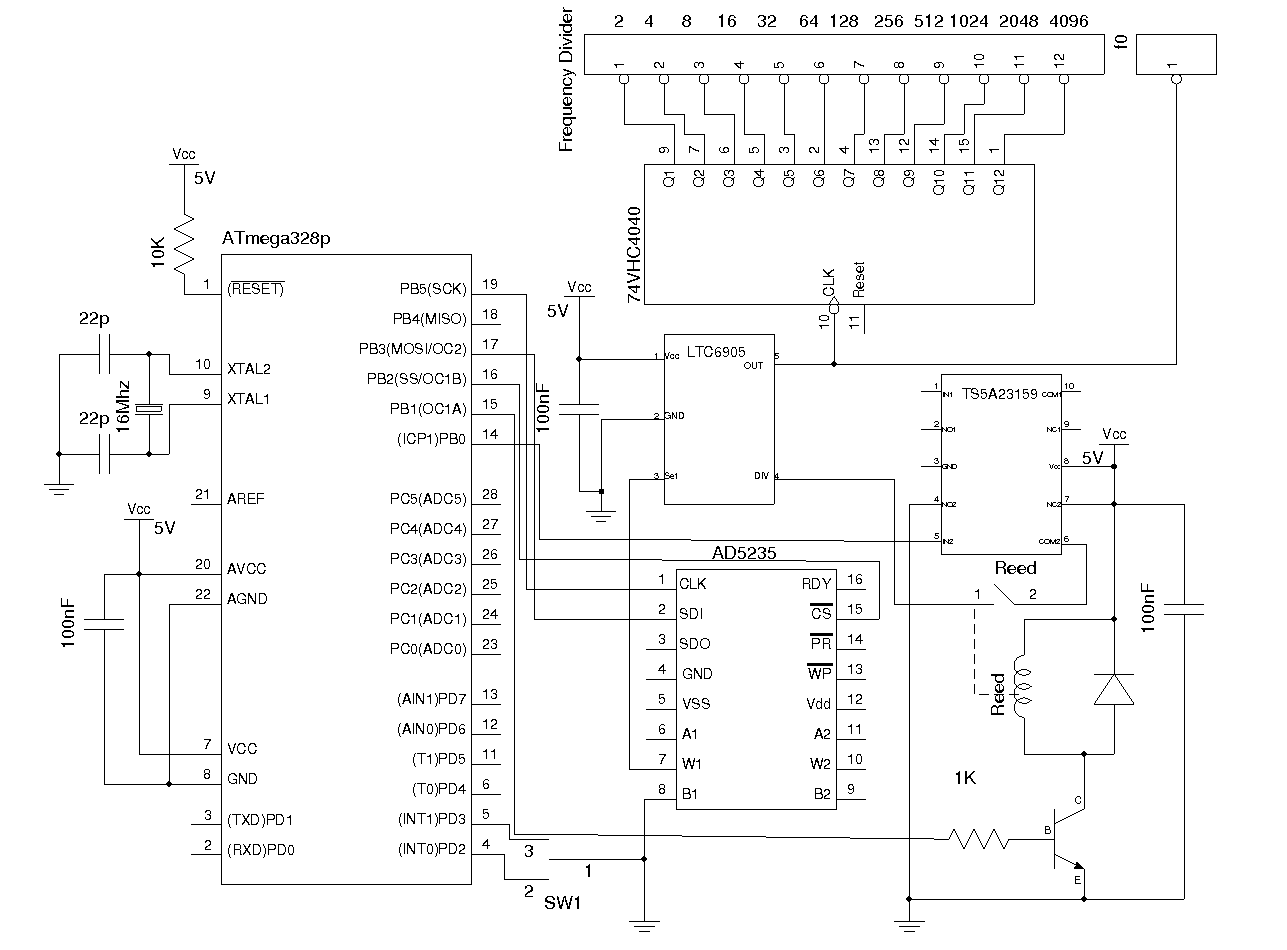
Most commercial-grade signal generators provide more than just sinusoidal waveform output, but they tend to be expensive for casual use. This article presents a simple wideband signal generator built around Linear Technology's LTC6905 Silicon Oscillator, capable of generating frequencies...