
Digitally Controlled Sine-Wave Generator

This circuit utilizes a harmonic filter to transform a square wave input into a sine wave output. The primary function of this circuit is to eliminate unwanted harmonics present in the square wave signal, which can distort the desired sine wave form.
The circuit typically consists of a low-pass filter that allows only the fundamental frequency of the square wave to pass while attenuating higher frequency harmonics. This can be achieved using passive components such as resistors, capacitors, and inductors, or through active components like operational amplifiers configured in a filter topology.
To ensure the output sine wave is adjustable, the circuit may incorporate variable components, such as potentiometers or variable capacitors, which allow for tuning of the filter characteristics. This adjustability can help in achieving the desired amplitude and frequency of the sine wave output.
In practical applications, the circuit may also include a feedback mechanism to monitor the output waveform, ensuring that it closely resembles a true sine wave. This can be implemented using additional operational amplifiers and comparators to refine the output further.
Overall, the design must consider factors such as component tolerances, frequency response, and load conditions to ensure the generated sine wave is of high fidelity and suitable for its intended application.By removing harmonics from a square wave, this circuit generates an accurate and adjustable sine-wave output.. 🔗 External reference
Related Circuits
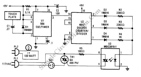
This is a three-mode lamp dimmer circuit with touch control. This circuit can be used to control a lamp in three operation modes: dim, off, and bright. A NE555 timer is utilized in the design. The three-mode lamp dimmer circuit...
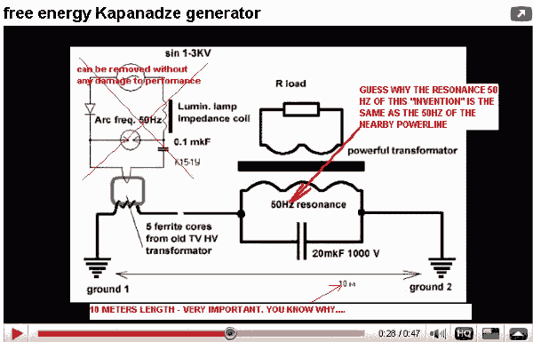
An inventor from the Republic of Georgia, Tariel Kapaladze, claims to have developed a 5-kilowatt free energy generator. In a demonstration video, the device seemingly produces large amounts of energy without any visible source. While it appears to extract...
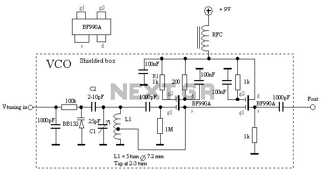
The VCO is based on a Hartley oscillator. The frequency is determined by L1 and capacitor C1. The tuning voltage will change the capacitance in the varactor BB132 which will change the oscillation frequency. The value of capacitor C2...
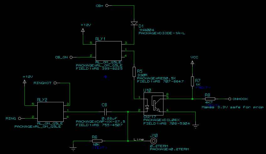
A four-channel DMX512 controlled ringer. The Mk 3 will also incorporate a ringing supply generator, making it reproducible by those without access to the BT ringing supply Number 7. The ringer is microprocessor-controlled, utilizing a Parallax Propeller-based chip, specifically...
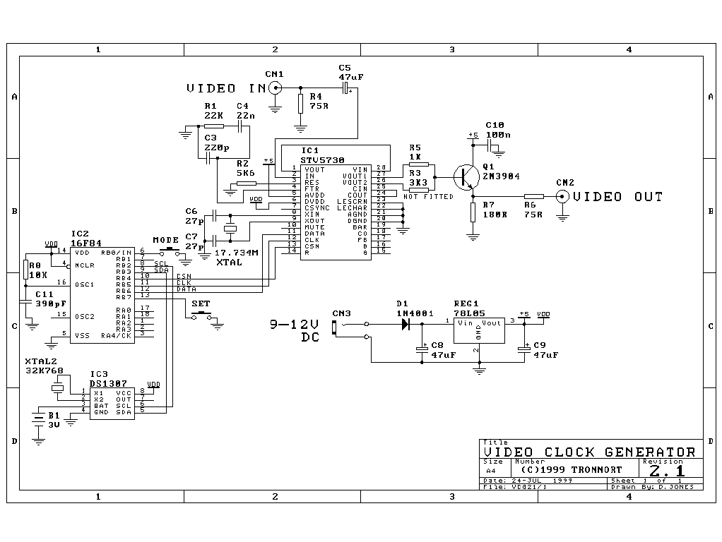
The following design is capable of overlaying the time and date onto any existing PAL (or optionally NTSC) composite video signal. It is housed in a very neat and compact standard moulded casing and has standard 75ohm RCA video...
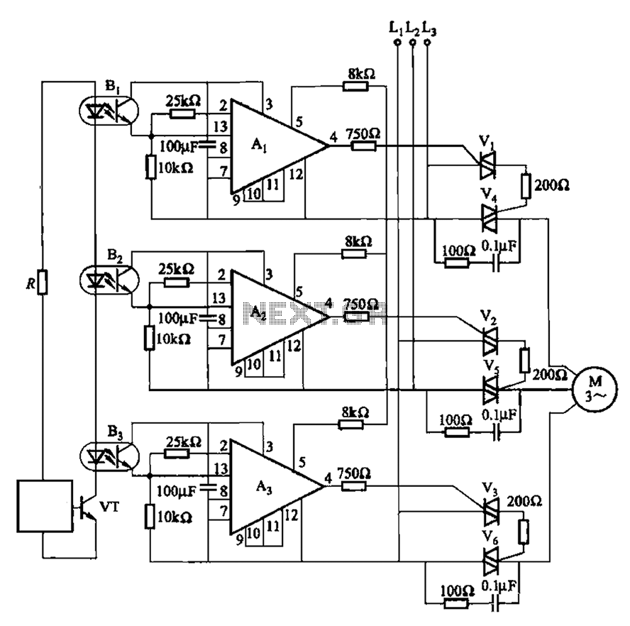
The 331 circuit depicted in the figure utilizes a two-way thyristor for controlling the start and stop functions of a motor. It operates without mechanical contacts, generating no noise or sparks, making it suitable for applications that require frequent...