
Touch-Controlled Lamp Dimmer

The three-mode lamp dimmer circuit employs a NE555 timer integrated circuit (IC) configured in a monostable or astable mode, depending on the specific design requirements. The touch control feature allows users to switch between the three states—dim, off, and bright—through a simple capacitive touch interface, eliminating the need for mechanical switches.
In the circuit, the NE555 timer generates a pulse width modulation (PWM) signal that is used to control the brightness of the lamp. The duty cycle of this PWM signal can be adjusted based on the touch input, allowing for smooth transitions between the different brightness levels.
The touch sensor can be implemented using a capacitive touch pad connected to the input of the NE555 timer. When the pad is touched, it triggers the timer to change its output state. The output from the NE555 is then fed into a transistor or a triac, which acts as a switch to control the power delivered to the lamp.
Additional components may include resistors and capacitors that set the time constants for the NE555 timer, ensuring that the response to touch inputs is both quick and reliable. A diode may also be included for flyback protection if an inductive load is used.
Overall, this circuit design provides an efficient and user-friendly method for controlling lamp brightness, enhancing both functionality and aesthetics in various lighting applications.This is a three-modes lamp dimmer circuit with touch control. This circuit can be used to control a lamp in 3 operation modes: dim, off, and bright. A NE555 . 🔗 External reference
Related Circuits
This is a portable, high-power incandescent electric lamp flasher. It functions as a dual flasher (alternating blinker) capable of managing two independent 230V AC loads (bulbs L1 and L2). The circuit is entirely transistorized and operates on battery power....
The electronic pest-killing lamp circuit comprises an oscillator, control circuit, high voltage generator, LED indicator circuit, and power supply circuit. The schematic diagram illustrates these components. The oscillator circuit includes a time-base integrated circuit (IC), resistors R5 to R7,...
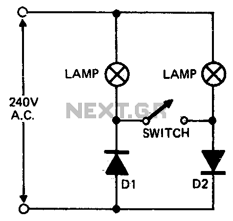
When setting up photographic floodlamps, it is sometimes desirable to operate the lamps at lower power levels until actually ready to take the photograph. The circuit allows the lamps to operate on half-cycle power when the switch is open...
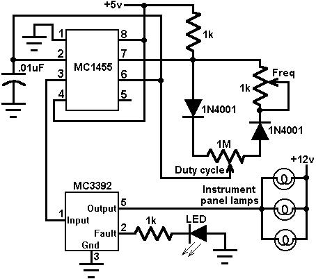
This circuit utilizes an MC3392 low-side protected switch along with an MC1455 timing circuit to create a dimmer control for automotive instrumentation panel lamps. The brightness of incandescent lamps can be adjusted by applying Pulse Width Modulation (PWM) to...
This is a dual-color lamp designed to illuminate the codes printed on transistors and integrated circuits (ICs). The codes and numbers on the black bodies of these components can be challenging to read in low light conditions due to...
The diagram illustrates a human infrared remote sensing lamp circuit. It utilizes the trace infrared heat emitted by humans to control the lamp's operation, allowing it to turn on or off remotely. This human infrared remote sensing lamp features...