
Ding-dong electronic doorbell

The electronic doorbell circuit operates through several interconnected modules that ensure the functionality of the doorbell system. The power supply circuit is crucial for converting the mains voltage to a lower, usable voltage for the other components. The power transformer (T) steps down the voltage, while the rectifier diodes (VD1-VD4) convert the AC voltage to DC. The filter capacitor (C1) smooths the rectified voltage to provide a stable power source for the circuit.
The trigger control circuit is activated when the doorbell button is pressed. This circuit includes a control circuit (S) that manages the flow of current to the audio oscillator. The diode (VD5) protects the circuit from reverse polarity, while capacitor (C2) and resistors (R1, R2) help in shaping the signal and ensuring proper operation of the trigger circuit.
The audio oscillators are responsible for generating the sound output of the doorbell. Audio oscillator A utilizes diodes (D1, D2) within a NAND gate IC (D1-D4) along with resistor (R3) and capacitor (C3) to create a specific frequency tone. Audio oscillator B, on the other hand, employs diodes (D3, D4) within the same IC, a potentiometer (RP) for volume control, and capacitor (C4) to stabilize the oscillation frequency.
Finally, the audio output circuit converts the oscillating signals into audible sound. This section consists of resistors (R4, R5) which limit the current to the audio output, diodes (VD6, VD7) that provide signal protection, and a transistor (V) that amplifies the audio signal. The speaker (BL) then produces the sound that alerts the user when someone presses the doorbell.
Overall, the integration of these components allows for a reliable and efficient electronic doorbell system, providing both functionality and user-friendly operation.The ding-dong electronic doorbell circuit is composed of the power supply circuit, trigger control circuit, audio oscillator output circuit, and it is shown in Figure 3-125. Power supply circuit is composed of the power transformer T, rectifier diodes VDl-VD4 and filter capacitor Cl.
Trigger control circuit is composed of the doorbell button, cont rol circuit S, diode VD5, capacitor C2 and resistors Rl, R2. Audio oscillator A consists of the Dl, D2 which are inside of four NAND gate IC (Dl-D4) and resistor R3, capacitor C3. Audio oscillator B consists of the D3, D4 which are inside of IC and potentiometer RP, capacitor C4. Audio output circuit consists of resistors R4, R5, diodes VD6, VD7, transistor V, and the speaker BL.
🔗 External reference
Related Circuits
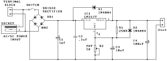
A potentiometer, designated as R2, can be utilized to adjust the desired output voltage. The kit is capable of accepting either AC or DC input through a socket or terminal block. It is advisable to incorporate protection diodes when...
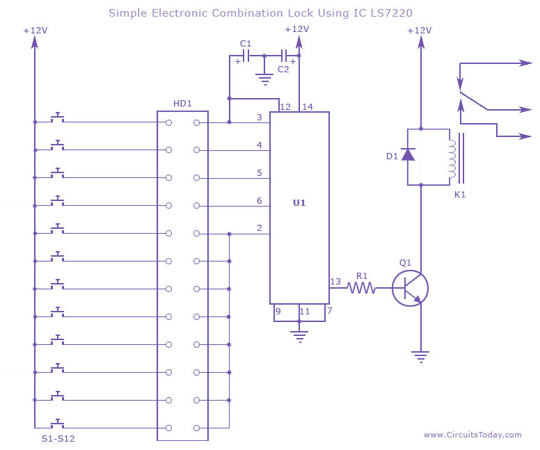
This circuit diagram illustrates a simple electronic combination lock utilizing the IC LS7220. It is designed to activate a relay for controlling any device (on & off) when a specific combination of four digits is entered. The circuit operates...
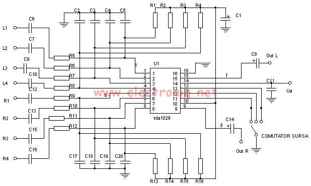
The TDA1029 is a dual operational amplifier configured as an impedance converter. Each amplifier features four mutually switchable inputs that are safeguarded by clamping diodes. Signal sources can be switched in various modes. The electronic components required for this...
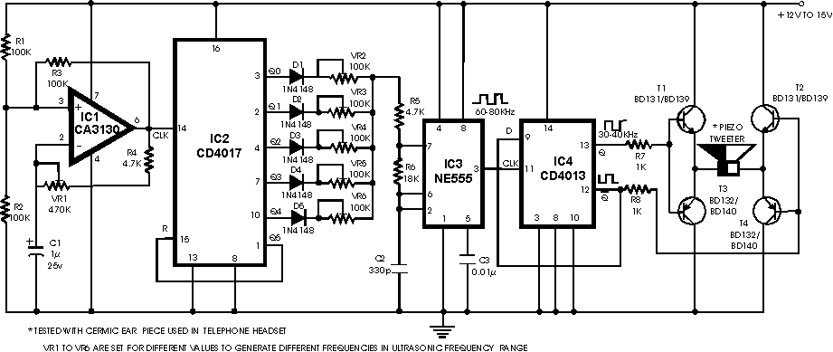
There are many ultrasonic pest repellent devices available on the market, but a major drawback is that their power output is low and their effectiveness suffers. Ultrasonic pest repellent devices utilize high-frequency sound waves to deter pests such as rodents...
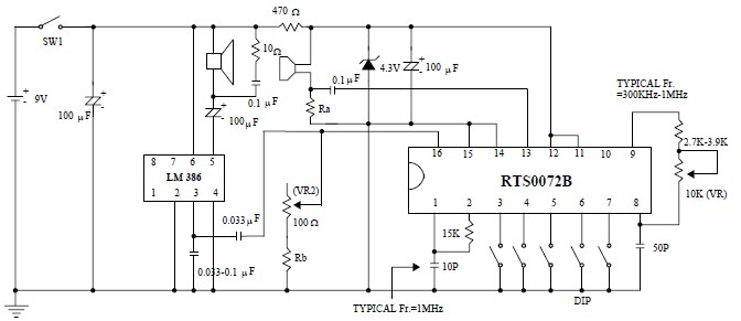
This voice changer circuit diagram is an electronic project developed using the RTS0072B single-chip CMOS LSI, specifically designed for voice-changing applications. It can transpose or distort one voice into another by encoding the input audio signals at normal speed...
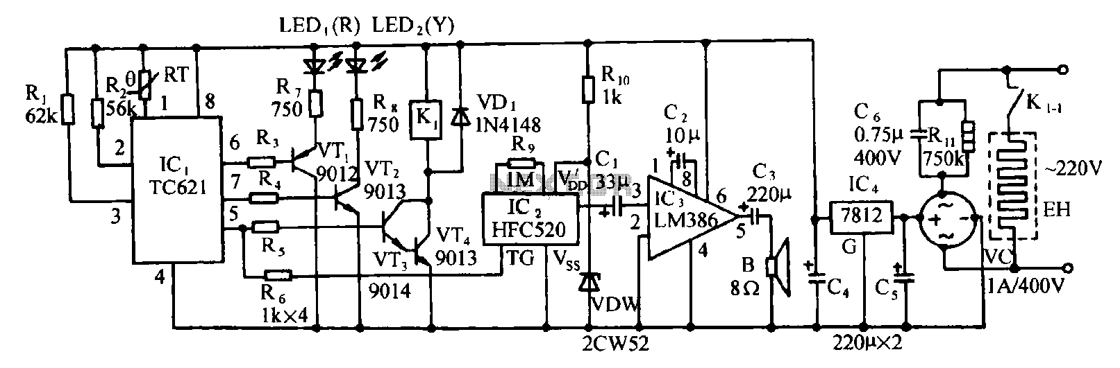
Eggs hatch chicks at temperature requirements within the range of 36 to 39 degrees Celsius. The temperature sensor integrated circuits utilize the TC621 temperature control circuit, which has fewer external components, is low cost, and offers high reliability. Users...