
Electronic Combination Lock Circuit using IC LS 7220

The electronic combination lock circuit utilizing the LS7220 IC is a practical solution for access control in various applications. The IC functions as a digital lock, capable of recognizing a user-defined four-digit code. The power supply range of 5V to 12V provides flexibility in design and application, ensuring compatibility with a wide range of devices.
The four-digit combination is established by connecting switches to designated pins on the IC. Each switch corresponds to a specific digit in the combination, allowing for customizable security codes. The reset function, activated by connecting additional switches to pin 2, enhances security by requiring re-entry of the code upon an incorrect input, thereby preventing unauthorized access.
The relay output is a crucial feature, enabling the control of external devices such as alarms, lights, or locks. The timing of the relay activation is adjustable through the selection of capacitor C1. A capacitor value of 1000 µF, for instance, will yield an activation time of approximately 6 seconds, but this can be modified to suit specific requirements by using capacitors with higher capacitance values.
For the keypad interface, arranging the switches in a 3x4 matrix format optimizes space on the PCB while providing an intuitive user experience. The choice of labeling the keys with symbols instead of numbers further enhances security by complicating unauthorized attempts to guess the combination. This design consideration can deter potential intruders, as the symbols may not be immediately recognizable as numerical inputs.
Overall, this electronic combination lock circuit presents a robust and adaptable solution for secure access control, with user-friendly features and customizable options to meet diverse security needs.This is the circuit diagram of a simple electronic combination lock using IC LS 7220. This circuit can be used to activate a relay for controlling (on & off) any device when a preset combination of 4 digits are pressed. The circuit can be operated from 5V to 12V. To set the combination connect the appropriate switches to pin 3, 4, 5 and 6 of the IC th rough the header. As an example if S1 is connected to pin 3, S2 to pin 4, S3 to pin 5, S4 to pin 6 of the IC, the combination will be 1234. This way we can create any 4 digit combinations. Then connect the rest of the switches to pin 2 of IC. This will cause the IC to reset if any invalid key is pressed, and entire key code has to be re entered.
When the correct key combination is pressed the out put ( relay) will be activated for a preset time determined by the capacitor C1. Here it is set to be 6S. Increase C1 to increase on time. For the key pad, arrange switches in a 3X4 matrix on a PCB. Write the digits on the keys using a marker. Instead of using numbers I wrote some symbols!. The bad guys will be more confused by this. 🔗 External reference
Related Circuits
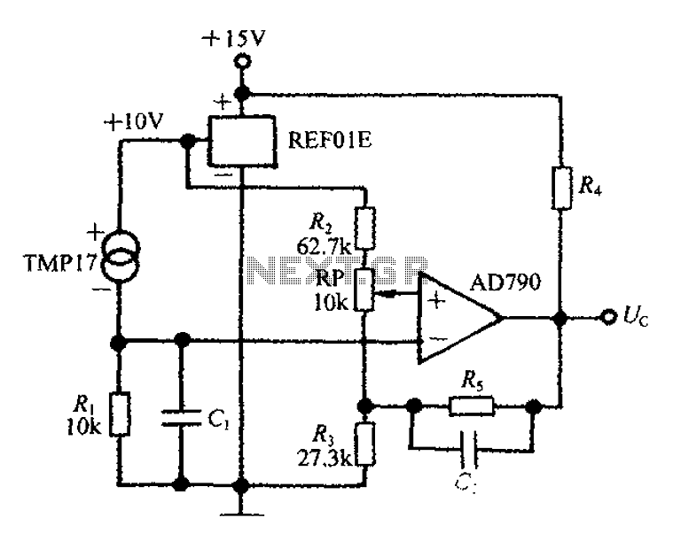
An adjustable thermostat controller circuit is widely used in everyday applications, such as for maintaining a constant temperature in soldering irons. The circuit utilizes the TMP17 sensor along with the REF01E voltage reference to ensure a stable 10V supply...
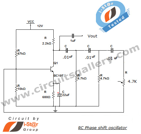
This section introduces a transistor oscillator circuit known as the RC Phase Shift Oscillator. An oscillator is an electronic circuit that functions as a sine wave generator, requiring only a DC power supply. It is commonly used in variable...
The image below depicts a block diagram of a complete mixer that consists of four input amplifier modules followed by four switchable tone management modules, one stereo line input, four mono main faders, one stereo dual-ganged main fader, four...
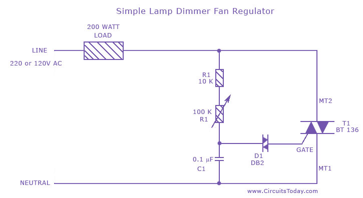
A fan regulator circuit that can also function as a simple lamp dimmer circuit. This fan speed regulator or light dimmer operates based on power control using a triac. The fan regulator circuit is designed to control the speed of...
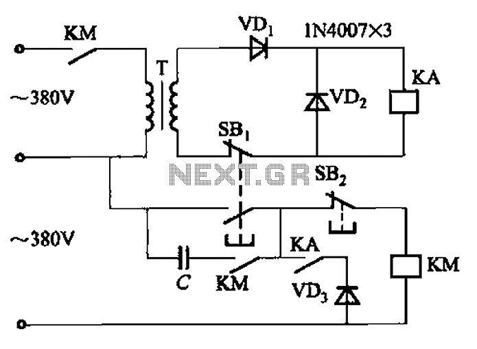
The AC contactor DC transformer circuit operates using various types of transformers and AC contactors in a DC application. The AC contactor DC transformer circuit is designed to control and manage electrical power in applications where alternating current (AC) is...
A guitar to MIDI interface was designed to serve as an interface between guitar playing and MIDI control of external hardware and software. This document describes the details of the design, experimentation, implementation, and final outcome of the project....