
Diode Radio For Low Impedance Headphones

The design of a vintage detector radio requires careful consideration of component specifications, particularly the impedance of the headphones used. The traditional specification of 2000 ohms (2 G) for headphones is crucial for optimal performance, as lower impedance headphones (32 ohms) may not effectively match the circuit's requirements. To adapt modern headphones, a transformer from a mains adapter can be employed. This transformer should feature multiple output voltage taps, allowing for flexibility in impedance matching.
The antenna coil plays a vital role in the radio's reception capability. Constructed on a ferrite rod, the coil's dimensions and the number of turns are specifically chosen to enhance medium wave reception. The presence of tap points at intervals of 10 turns enables fine-tuning of the antenna's performance, allowing the user to select the most effective configuration for their environment.
In addition to the antenna coil, the external aerial significantly impacts reception quality. Utilizing metal infrastructure, such as guttering and pipes, as an aerial can enhance signal capture, provided these elements are not grounded. This setup takes advantage of the conductive properties of metal to improve reception, particularly in areas with strong broadcast signals.
Overall, this circuit design illustrates the adaptability of modern components for use in traditional radio applications, emphasizing the importance of impedance matching and the strategic use of available materials to optimize performance.If you ever look at construction notes for building old detector type radios the type of headphones specified always have an impedance of 2 G— 2000. Nowadays the most commonly available headphones have an impedance of 2 G— 32 , this relatively low value makes them unsuitable for such a design.
However, with a bit of crafty transformation the se headphones can be used in just such a design. To adapt them, you will need a transformer taken from a mains adapter unit, the type that has a switchable output voltage (3/4. 5/6/9/12 V) without the rectifying diodes and capacitor. Using the different taps of this type of transformer it is possible to optimize the impedance match. For the diode radio (any germanium diode is suitable in this design) the key to success is correct impedance matching so that none of the received signal energy is lost.
The antenna coil on the 10 mm diameter by 100 mm long ferrite rod is made up of 60 turns with a tap point at every 10 turns; this is suitable for medium wave reception. If a long external aerial is used it should be connected to a lower tap point to reduce its damping effect on the circuit.
You can experiment with all the available tapping points tond the best reception. With such a simple radio design, the external aerial will have a big in‚uence on its performance. If your house has metal guttering and rain water pipes, it will be possible to use these as an aerial, as long as they are not directly connected to earth. Those who live in the vicinity of a broadcast transmitter may be able to connect a loudspeaker directly to the output or if the volume is too low, why not try connecting the active speaker system from your PC
🔗 External reference
Related Circuits
A very simple circuit for an FM receiver that does not require an integrated circuit (IC) and utilizes only a single transistor. The functionality of this transistor is uncertain. This design represents a regenerative or super-regenerative radio receiver. There...
The thermostat can be set, and it specifies the lower limit of the circuit diagram. The thermostat in the circuit is a critical component used to regulate temperature by controlling the heating or cooling system. It operates by comparing the...
In a previous article on constructing a radio, a simple crystal radio receiver circuit was discussed. The schematic presented here is also a straightforward AM radio circuit; however, it does not utilize a crystal but instead employs a high-gain...
The concept of distributed active RIAA correction and the use of negative feedback to linearize the input stage is appealing. However, the original design by Collin has significant flaws, including poor power supply rejection ratio (PSRR) in the input...
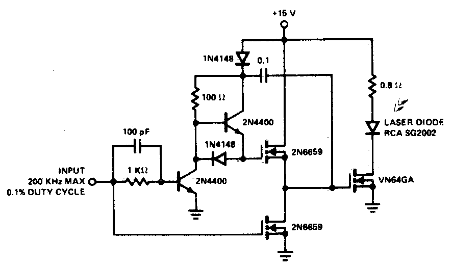
A faster driver can supply a higher peak gate current to switch the VN64GA very quickly. The circuit uses a VMOS totem pole stage to drive the high power switch. The described circuit employs a VMOS (Vertical Metal Oxide Semiconductor)...
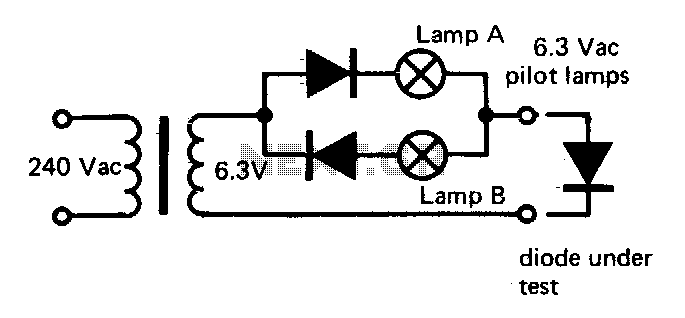
If lamp A or B is illuminated, the diode is functional. If both lamps are illuminated, the diode is short-circuited. If neither lamp lights up, the diode is an open circuit. The described circuit utilizes two indicator lamps, designated as...