
Diode tester using PIC 16F84


The described circuit utilizes a PIC 16F84 microcontroller to function as a diode tester, facilitating a straightforward method for assessing the health of diodes. The microcontroller is configured to read the status of the diode through its GPIO pins, specifically PB0, PB3, and PA0.
During the testing procedure, the microcontroller sets PB0 to a logical high ("1") and PB3 to a logical low ("0"). This configuration allows for the testing of the diode's forward bias condition. If the diode is functioning correctly, PA0 will read a logical high ("1"), indicating that the diode is conducting. Conversely, if PA0 reads a logical low ("0"), it indicates a fault in the diode.
The microcontroller's firmware is programmed to respond to the readings from PA0 by controlling two LEDs: a green LED and a red LED. When PA0 is high ("1"), the green LED is illuminated, signaling that the diode is operational. If PA0 is low ("0"), the red LED lights up, indicating a defective diode.
The testing can also be performed in a continuous mode by reversing the states of PB0 and PB3, setting PB0 to "0" and PB3 to "1". This allows the microcontroller to assess the diode under reverse bias conditions. The same logic applies: a high reading on PA0 indicates a good diode, while a low reading indicates a failure.
This circuit can be implemented on a breadboard or a custom PCB, with all necessary components including the PIC 16F84 microcontroller, resistors for current limiting on the LEDs, and the diodes to be tested. Proper power supply connections must be made to ensure the microcontroller operates within its specified voltage range. This design provides a practical and efficient method for testing diodes in various applications, making it a valuable tool for both hobbyists and professionals in electronics.This is a simple use of the PIC 16F84 about a diode tester. Test procedure : We set «1» to PB0 and «0» to PB3. If diode is ok and opens, then at PA0 we have «1». If PA0 is «0», then the the diode has problem. With the program we manage what the PIC will do in each situation . If PA0 is «1», green led lights wich means that the diode is OK and if PA0 is «0» red led is lighting and the diode is problematic Test continuous as follows: We give «0» at PB0 and «1» to PB3. If diode is OK and opens, then at PA0 is «1». If PA0 is «0», then diode has problem. If PA0 is «1», green led lights that means that diode is OK and if PA0 is «0» the red diode is lights that means the the diode is problematic. 🔗 External reference
Related Circuits
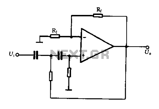
A typical two high-pass filter circuit. A high-pass filter (HPF) is an electronic circuit that allows signals with a frequency higher than a certain cutoff frequency to pass through while attenuating signals with frequencies lower than the cutoff frequency. A...
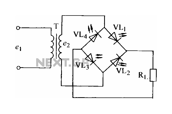
In certain applications, the current from a non-rectified voltage power supply circuit is insufficient. A light-emitting diode (LED) rectifier circuit can be employed to address this issue, serving as a power indicator. It is important to ensure that the...
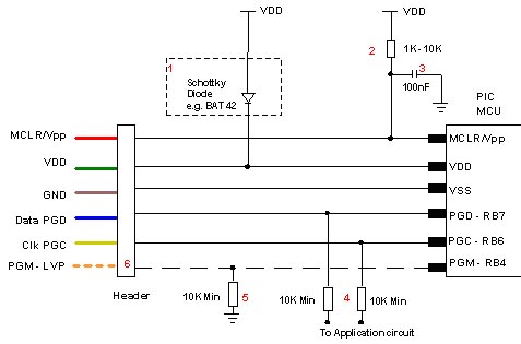
Microchip does not recommend any specific circuit for In-Circuit Serial Programming (ICSP). Various diagrams exist for different tools, such as Pro Mate and PICKit2, which feature similar circuitry with minor variations. Some schematics may suggest resistor values that are...

This board layout was created using the SOIC version of a PIC16F627A without drawing the usual schematic first. Most of the part values are etched on the Layout. The SIP resistor packs I used are 10k ohm, some experimentation...
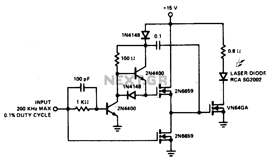
A faster driver can supply higher peak gate current to switch the VN64GA very quickly. The circuit uses a VMOS totem pole stage to drive the high power switch. The described circuit employs a high-speed driver to enhance the switching...
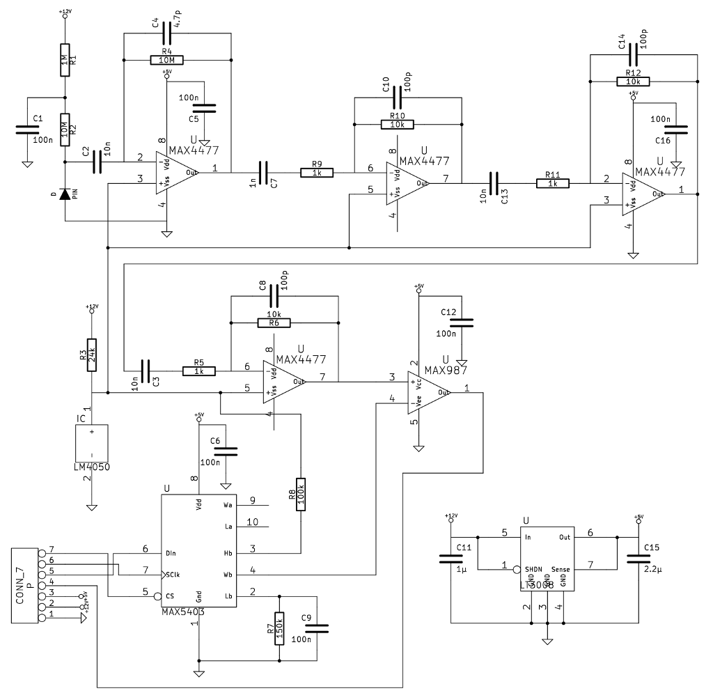
A noteworthy application note from Maxim detailed a gamma-photon detector utilizing a standard PIN diode as its sensing element. The circuit design appeared straightforward, prompting the decision to construct it, as having multiple measurement instruments is always beneficial. The gamma-photon...