
Light-emitting diode rectifier circuit

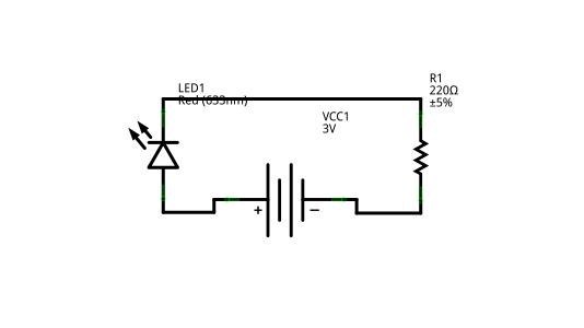
The proposed circuit utilizes a half-wave rectifier configuration, which is a simple yet effective method for converting alternating current (AC) to direct current (DC). In this arrangement, an LED is connected in series with a diode, which allows current to flow in only one direction. The diode conducts during the positive half-cycle of the AC waveform, enabling the LED to illuminate. However, during the negative half-cycle, the diode blocks the current, preventing the LED from lighting up.
To design this circuit, a transformer may be included to step down the AC voltage to a suitable level for the LED. The diode should be selected based on its peak inverse voltage (PIV) rating, which must exceed the maximum voltage of the AC supply to prevent breakdown. The LED's forward voltage drop and forward current specifications must also be considered to ensure optimal performance and longevity.
A resistor may be added in series with the LED to limit the forward current, thus protecting the LED from overcurrent conditions. The value of this resistor can be calculated using Ohm's Law, taking into account the supply voltage, the forward voltage of the LED, and the desired forward current.
This half-wave rectifier circuit can be effectively used in low-power applications where a simple and compact solution is required for indicating power status through an LED. Careful selection of components and adherence to specifications will ensure reliable operation and visual indication of power availability.In some of the requirements and the current is not rectified voltage power supply circuit is not high, can be used to form a light emitting diode rectifier circuit, and power indicator cater to. Be careful not to exceed the maximum light-emitting diode forward current. Half-wave rectifier:
Related Circuits
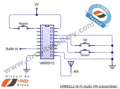
This article provides the circuit schematics for an FM transmitter along with the necessary explanations. The primary component utilized is the VMR6512 IC, a highly integrated FM audio signal transmitter chip designed for Hi-Fi audio applications. This chip can...
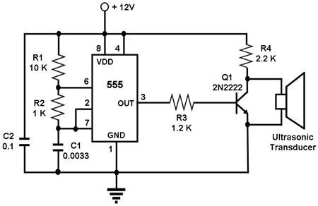
The circuit utilizes a 555 timer integrated circuit (IC) configured as an astable multivibrator, which generates a continuous signal at a specific frequency as long as its reset pin (pin 4) is held high. The ultrasonic transducer employed in...

The CP2128 is a low-noise, fixed-frequency step-up DC/DC converter designed for garden applications. It operates within an input voltage range of 2.7V to 4.5V and can generate a stable output voltage of 5V, with a maximum output current of...
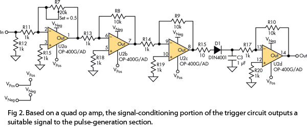
This version of the trigger circuit for the stop-motion camera system utilizes an electret microphone for sonic input, although it can be replaced with an LED and photodiode pair for optical triggering. A recent home-built project involved constructing a...
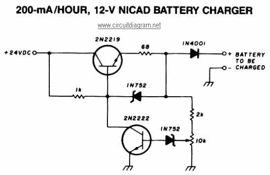
A 12V NiCAD battery charger circuit with a charging rate of 200mA per hour. This circuit initially charges the battery at 75mA until it reaches a full charge, after which the current is reduced to a trickle rate. The...
Creating circuit boards can be a challenging task. It requires designing a schematic, testing it on a breadboard, laying out the board, and finally printing and etching the board. Fortunately, Fritzing offers a solution. Fritzing is a free, open-source...