
Direct-coupled Single-Ended (SE) 6V6 / 6V6GT Tube Amplifier Schematic
 6V6 / 6V6GT Tube Amplifier")
The described circuit represents a direct-coupled single-ended tube amplifier utilizing 6V6 or 6V6GT vacuum tubes, which are well-regarded for their warm sound characteristics and suitability for audio amplification. The ECC83 (also known as 12AX7) serves as the driver stage, providing high gain and low noise, which is essential for achieving quality audio output.
In this schematic, the signal path begins at the input stage, where an audio signal is fed into the ECC83 tube. The ECC83 operates in a common cathode configuration, allowing it to amplify the input signal before passing it to the output stage. The direct coupling between the ECC83 and the 6V6 tubes eliminates the need for coupling capacitors, which can introduce phase shifts and frequency response alterations, thus preserving the integrity of the audio signal.
The output stage consists of one or more 6V6 tubes, which are configured in a single-ended arrangement. This configuration is known for producing a rich, harmonic distortion that is often perceived as musically pleasing. The output transformer plays a crucial role in matching the high impedance of the tubes to the lower impedance of the speakers, ensuring efficient power transfer and optimal sound reproduction.
Power supply considerations are also critical in this design. The circuit requires a high-voltage DC supply for the anodes of the tubes and a lower voltage for the ECC83. Proper filtering and regulation of the power supply are essential to maintain stability and minimize noise in the audio output.
Overall, this amplifier design exemplifies classic tube amplification principles, emphasizing simplicity, direct coupling, and the use of high-quality components to achieve a desirable sound profile for audio enthusiasts.Direct-coupled Single-Ended (SE) 6V6 and 6V6GT Tube Amplifier Schematic with ECC83 Driver Stage. From the book Build your own Audio Valve Amplifier by Rainer zur Linde. 🔗 External reference
Related Circuits
A schematic diagram is a layout of symbols and connections representing every electronic component in a circuit, serving as a guide to understanding how the circuit functions. Learning to read these diagrams may initially seem challenging, but it is...
A simple audio amplifier application using a TL431 voltage regulator. The amplifier is designed to produce room-filling sound from a standard clear radio equipped with a long-wire antenna and suitable ground. The chip is similar in complexity to a...
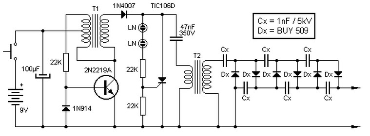
This high voltage source consists of an inverter built around a transistor that generates pulses of 150V. These pulses are supplied to an inverter made of a thyristor and a capacitor, which is connected in series with transformer T2....
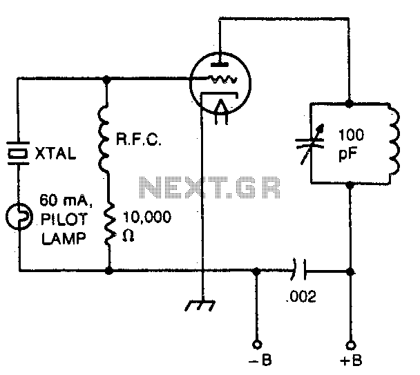
The pilot lamp limits current to prevent damage to the crystal. A very useful circuit. The circuit incorporates a pilot lamp designed to limit the current flowing to a crystal component, thereby safeguarding it from potential damage due to excessive...
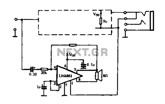
The circuit utilizes a MOSFET to automatically shut down the FIG system. When the headset is inserted, the contact opens, causing the MOSFET gate to connect to a high voltage, allowing current to pass. The LM4880 is configured to...
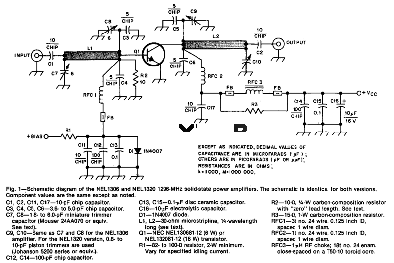
The design incorporates 30-ohm, 1/4 microstrip lines on the input and output. Capacitors C3, C4, C7, and C8, along with inductor L1, form a pi network that matches the low input impedance of the device to 50 ohms. Capacitors...