
Direct High Voltage DC Regulator

The circuit in question is designed to maintain a stable output voltage of 200V without the use of a transformer, which is a notable feature, particularly in applications requiring high voltage regulation. The absence of a transformer simplifies the design and can reduce the overall size and weight of the circuit.
In this setup, a high-voltage linear voltage regulator or a switching regulator may be employed to achieve the desired output. The circuit typically consists of essential components such as a voltage reference, error amplifier, pass transistor, and feedback network.
The voltage reference provides a stable reference point, ensuring that fluctuations in input voltage do not significantly affect the output. The error amplifier compares the output voltage to the reference voltage and adjusts the control signal to the pass transistor accordingly. This transistor acts as a variable resistor, dissipating excess voltage and maintaining the output at the set level.
Additionally, the circuit may include protection features such as over-voltage protection, thermal shutdown, and current limiting to enhance reliability and safety. Capacitors are often used at the output to filter any high-frequency noise, ensuring a clean voltage supply.
The design must account for the high voltage levels, necessitating the use of components rated for at least 200V, along with careful layout considerations to prevent arcing and ensure safe operation. Overall, this regulator circuit is suitable for applications requiring precise high-voltage regulation without the bulk and complexity of transformer-based designs.This regulator circuit stabilize the output voltage at 200V directly (without a transformer). Although the output voltage is high, this circuit only suffer a. 🔗 External reference
Related Circuits
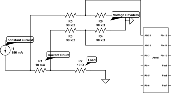
Measure current on a constant current source (LM317). Since a 3.3V chip is being used, a voltage divider is also required for reading the current. Will this circuit function correctly, or will it cause issues by attempting to increase...
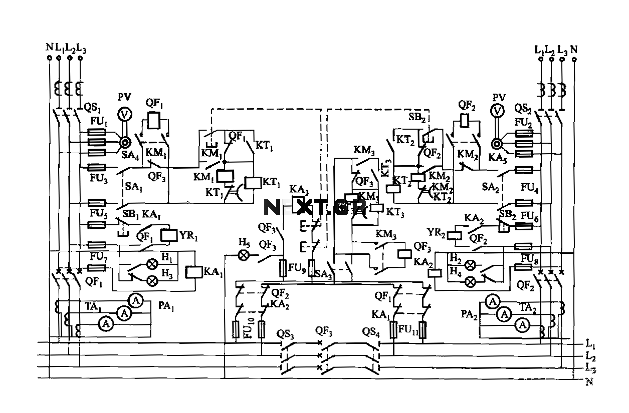
Dual power is provided for each complex, as the load is supplied through a two-way power system. In the event of a power outage, the contact switches transition from a closed position, allowing the power supply circuit to bear...
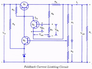
If the load resistance (RL) is reduced or the load terminals are accidentally shorted, a very large load current will flow, potentially damaging the pass transistor (Q1), diode, or other components. Fuse protection may not be sufficient, as the...
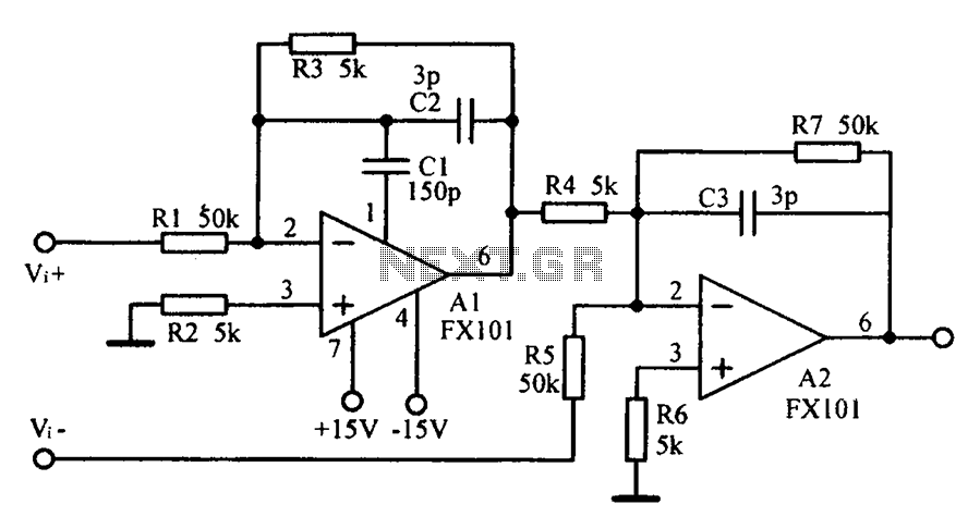
Common mode input voltage up to a difference of 100V enlarged circuit diagram. The circuit diagram described features a design capable of handling a common mode input voltage with a differential range of up to 100V. Such a configuration is...

These two comparators function as over-voltage and under-voltage comparators. In the first configuration, if the measured voltage (Vm) exceeds the reference voltage, the output of IC1 goes low. In the second configuration, if the input voltage (ViN) exceeds the...
The LM1036 is a DC-controlled circuit designed for tone adjustment (bass/treble), volume control, and balance. It is suitable for use in car radios, televisions, and audio systems. The circuit also incorporates loudness compensation. The LM1036 integrates several functionalities essential for...