
voltage measurement Measure current on a constant current source

To measure current from a constant current source like the LM317, a current sensing technique can be employed. The circuit typically consists of the LM317 configured in a constant current mode, where it regulates the output current to a desired level. The output current can be monitored using a shunt resistor placed in series with the load. The voltage drop across this resistor is proportional to the current flowing through it, following Ohm's Law (V = I * R).
Given that a 3.3V microcontroller or chip is being used, a voltage divider must be implemented to scale down the voltage across the shunt resistor to a level that the microcontroller can safely read. The voltage divider consists of two resistors connected in series. The output voltage from the divider can be calculated using the formula:
V_out = V_in * (R2 / (R1 + R2))
where V_in is the voltage across the shunt resistor, R1 is the resistor connected to the voltage source, and R2 is the resistor connected to ground. The values of R1 and R2 must be selected carefully to ensure that the output voltage does not exceed the maximum input voltage rating of the microcontroller's analog input pin.
It is crucial to ensure that the voltage divider does not load the circuit excessively, as this could interfere with the current measurement. The total resistance of the voltage divider should be high enough to minimize the impact on the current flowing through the shunt resistor while still allowing for a measurable voltage drop.
Potential issues that may arise include the possibility of the voltage divider affecting the current through the LM317, especially if the divider's impedance is not significantly higher than the load impedance. Additionally, proper consideration must be given to the power rating of the resistors used in the voltage divider, as they will dissipate power based on the voltage drop across them.
In conclusion, with careful design and consideration of component values, this circuit can function effectively for measuring current from a constant current source while interfacing with a 3.3V chip.Measure current on a constant current source(LM317), because I am using a 3v3 chip I also need a voltage divider to read it. Will this circuit work Or will it wreak havoc trying to increase voltage to drive current over the voltage dividers
🔗 External reference
Related Circuits
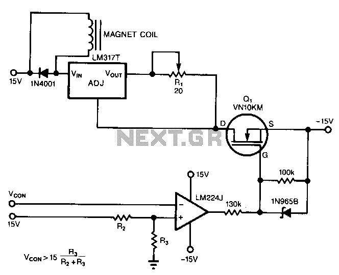
The circuit powers the load through the input of the regulator rather than its output. Due to the presence of a constant dummy load (R1) at the regulator's output, it attempts to draw a constant amount of current, regardless...
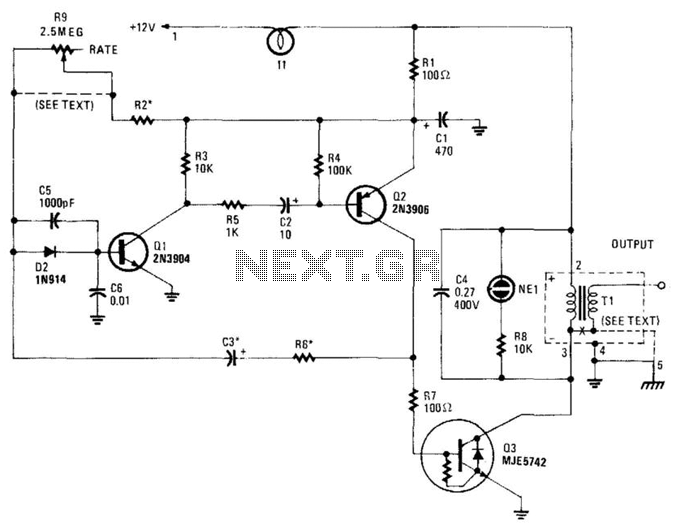
This high-voltage pulse supply generates pulses up to 30 kV. Q1 and Q2 form a multivibrator in conjunction with peripheral components R1 through R6, and C1, C2, C3, C5, C6, and D2. R9 adjusts the pulse repetition rate, while...
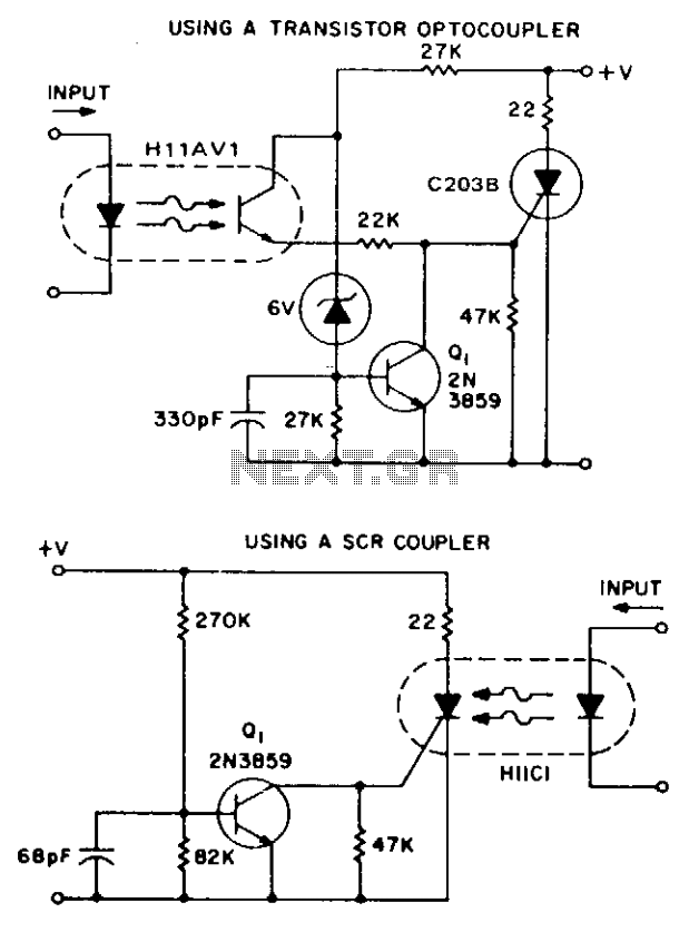
These two simple circuits provide zero voltage switching. They can be used with full wave bridges or in antiparallel to provide full wave control and are normally used to trigger power thyristors. If an input signal is present during...
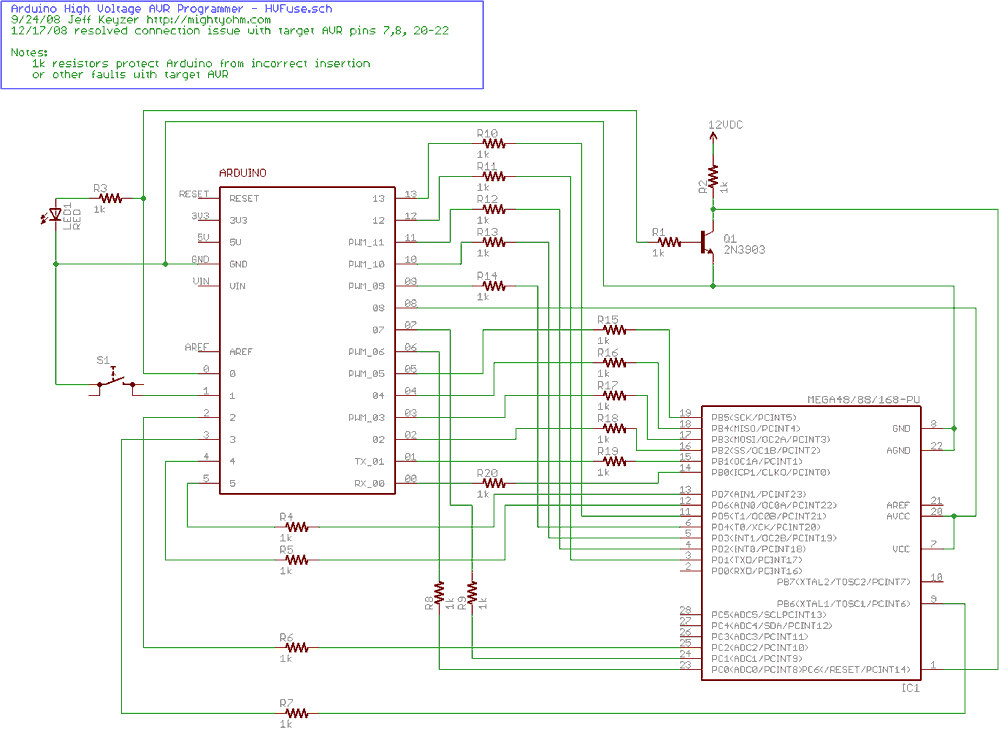
Fortunately, my trusty Arduino came to the rescue. I created an Arduino-based AVR programmer that uses the high voltage programming mode and can fix pesky fuses like RSTDISBL. The Arduino has just enough IO to implement the entire HV...
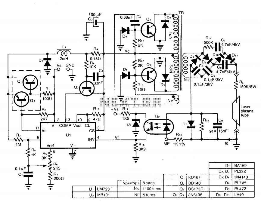
The circuit employs a free-running push-pull DC to DC high voltage converter to generate the required voltage for the laser plasma tube supply. The supply voltage (Vc) of this converter is regulated by a switch-mode power supply to maintain...

This is the design of a bias current compensation circuit. This circuit can operate with medium wattage source resistances while maintaining a minimal increase in the equivalent offset voltage. It is based on the LM11 operational amplifier. The circuit...