
Distance measurement system using PING Ultrasonic Range Finder

The PING Ultrasonic Range Finder circuit can be broken down into several key components and their interconnections. The PIC16F876A microcontroller serves as the central processing unit, executing the necessary algorithms to control the ultrasonic sensor and process the distance measurements. The microcontroller requires a stable power supply, which is provided by a voltage regulator that steps down the input voltage to the required 5V. The reverse polarity protection diode is essential to prevent damage to the circuit in case of incorrect power supply connections.
The ultrasonic sensor emits a high-frequency sound wave and listens for the echo that returns after bouncing off an object. The time taken for the echo to return is measured by the microcontroller, which calculates the distance based on the speed of sound. The formula used for calculating distance is Distance = (Time × Speed of Sound) / 2, where the speed of sound in air is approximately 343 meters per second.
The microcontroller is connected to an LCD display, which presents the calculated distance in a user-friendly format. The LCD is interfaced using a suitable communication protocol (often 4-bit or 8-bit mode), allowing the microcontroller to send commands and data to the display. A push button is included to initiate the measurement process, providing an interactive user experience. When pressed, the microcontroller triggers the ultrasonic sensor to emit a burst, waits for the echo, and subsequently processes the data to update the LCD with the distance measurement.
Overall, the PING Ultrasonic Range Finder circuit is a practical and efficient solution for distance measurement applications, combining simplicity and effectiveness in its design.A PING Ultrasonic Range Finder to build up a system which is capable of detect and measure the distance (in mm unit) of the closest object in front of the sensor. It is like a digital measuring tape where you point the sensor to an object, press the read button and the LCD will display the distance of the object in millimeter unit.
The PING) ultrasonic range finder is an easy to used sensor from Parallax. It can nicely detect the object in front with the distance from 2cm to 3m. The PING) sensor works by transmitting an ultrasonic burst and providing an output pulse that corresponds to the time required for the burst echo to return to the sensor. By measuring the echo pulse width, the distance to target can easily be calculated. The circuit for the system is quite simple. I am using PIC16F876A as the main controller. As usual, to operate the whole system, you need the power part which consist of on/off switch, power regulator, diode for wrong polarity protection and some capacitors.
You also need the basic components to support the operation of microcontroller like the crystal to generate clock, an active low push button for the master reset, programming port and some capacitors. For this project, I need to have a push button to input start read command and a LCD to display the output which is the distance value.
The connection for the Ping Ultrasonic sensor is also simple, the ground pin connect to the common ground of the circuit, the 5v connect to the circuit`s vdd and at last the signal pin connect to one of the I/O pin of the microcontroller. 🔗 External reference
Related Circuits
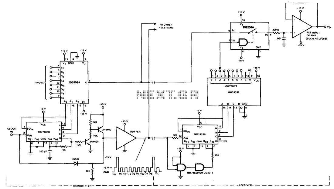
This circuit illustrates a typical multiplex system designed to transmit one of eight inputs to a remote location. A 5-V pulse train is transmitted through a separate channel to execute timing and synchronization functions. A 15-V reset pulse is...
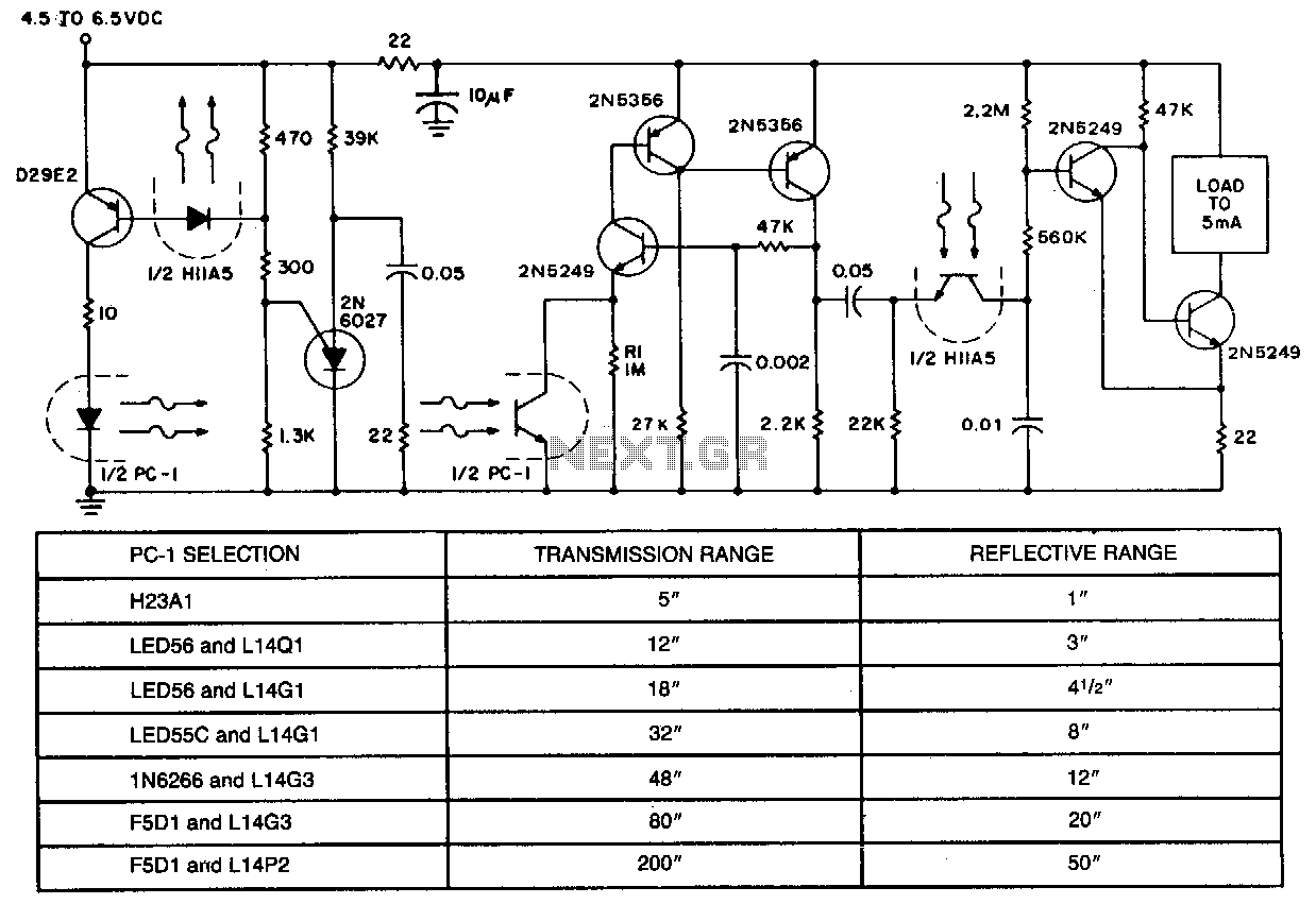
In applications requiring long-range operation with infrared (IR) light sources and high system reliability, pulsed-mode operation of the IR source is essential. Enhanced operational reliability is achieved through synchronous detection of the photodetector current, as implemented in this circuit....
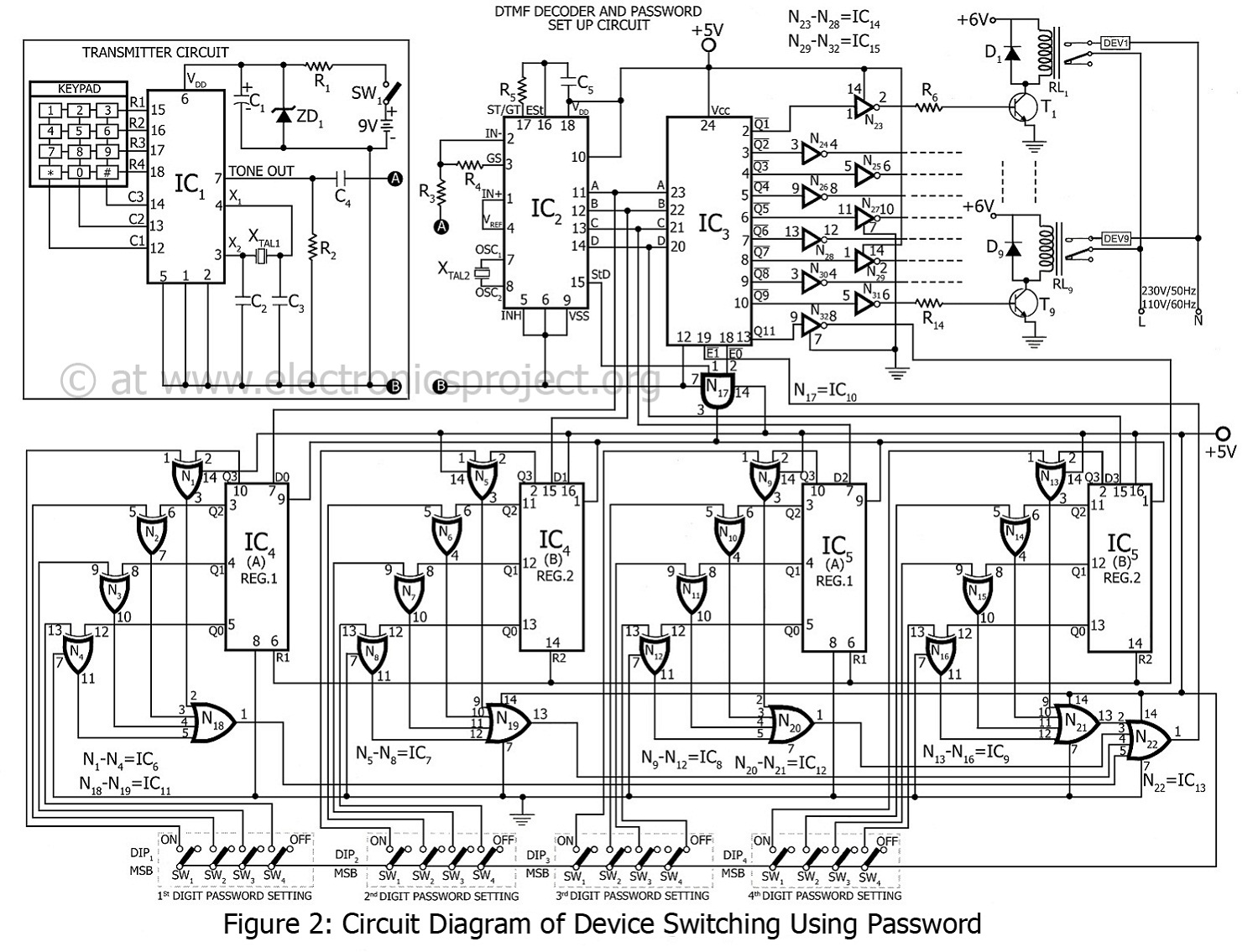
This project involves device switching using a password, developed by the innovative group Dreamlover Technology. It allows users to lock their devices with a password. The block diagram of the device switching system is presented in figure 1. The...
The induction coil detects the magnetic field flux during phone calls, amplifies the signal, and triggers the LED. These circuits are designed for the phone to rest on the pickup coil. The electromotive force (emf) from the bell electromagnets...
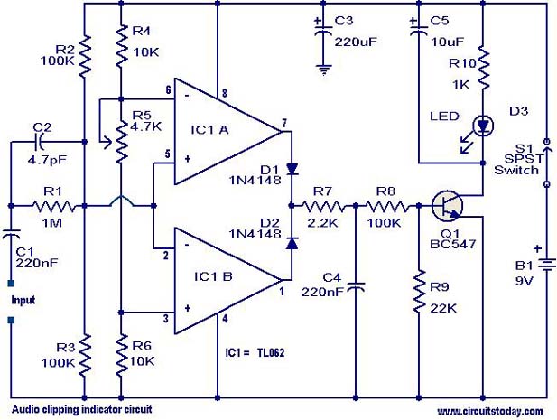
This circuit is designed to detect clipping in a specific waveform. Clipping occurs when the amplitude of a waveform decreases before reaching its expected limit. The circuit activates an LED as an indication that the tested signal is experiencing...
It is entirely feasible and acceptable to control various outputs while sitting at a PC terminal. A simple hardware circuit and software are utilized to interface with a 7-segment rolling display. The printer port of a PC provides a...