
Audio clipping indicator circuit

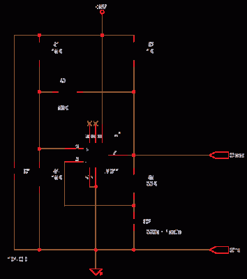
This circuit employs a window comparator configuration to effectively monitor signal integrity by detecting clipping events. The operational amplifiers in the TL082 IC serve as the core of the detection mechanism. Clipping is characterized by the inability of an amplifier to accurately reproduce input signals, resulting in distortion, which this circuit aims to identify.
The positive and negative peak detection is achieved through the op-amps, which compare the input signal against predefined threshold levels set through the potentiometer R1. When the signal exceeds these thresholds, the op-amps output a high signal that is processed by diodes D1 and D2. These diodes ensure that only the relevant signals are passed to the base of transistor Q1, which acts as a switch to control the LED indicator.
Capacitor C5 plays a crucial role in the circuit by providing a time delay that allows for the detection of transient clipping events. This feature is particularly important in audio applications where signals can change rapidly, and brief periods of clipping can be easily overlooked without this delay.
The versatility of this circuit makes it suitable for use in a wide range of audio equipment, including mixers, power amplifiers, and preamplifiers. By monitoring for clipping, users can take corrective measures to prevent distortion, ensuring optimal performance of audio systems. The adjustable threshold provided by potentiometer R1 allows for customization based on specific application requirements, making the circuit adaptable to various signal conditions.This circuit can be used to identify whether there is a clipping in a particular wave form. Clipping is a phenomenon in which the amplitude of a particular waveform drops before it reaches the expected limit. This circuit glows an LED as an indication if the signal under test has clipping. The circuit is very useful in sorting out distortion probl ems in amplifiers. The circuit is based on a window comparator based on the two opamps inside the IC1 (TL082). The circuit detects the positive or negative peak value reached by the input signal. The output of the opamp is combined by the two diodes D1 & D2 and drives the transistor Q1 to glow the LED. The capacitor C5 is employed to induce a small time delay in order to detect very fast and short peaks.
The POT R1 can be used to set the level of clipping at which the LED has to glow. The circuit can be used with almost all sorts of mixers, power amplifiers and preamplifiers. 🔗 External reference
Related Circuits
This circuit functions as a simple analog-to-digital interface with a resolution capability of 10 to 12 bits. A 10-bit resolution translates to 1024 counts or divisions of a full scale (FS), which is approximately equivalent to 3.5 digits or...

Design a low-cost 4- to 20-mA receiver circuit for control loops using an analog-to-digital converter (ADC). The design of a low-cost 4- to 20-mA receiver circuit is essential in industrial applications for monitoring and controlling processes. This current loop standard...
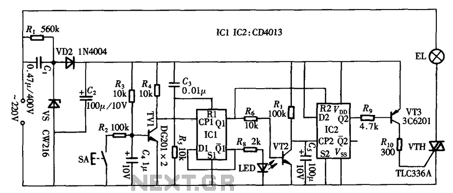
The circuit primarily utilizes a touch-delay switch composed of a pair of D flip-flops (CD4013). It can be employed in power switch applications for various machines. The delay switch can also function as a lighting control and features a...
Most homes today have at least a few infrared remote controls, whether for the television, video recorder, stereo, or other devices. Despite this, many individuals have experienced frustration when a light remains on after settling into a comfortable chair...
In its simplest form, a voice-over unit is just a microphone and change-over switch feeding an amplifier, the output from the microphone having priority over the amplifiers audio signal when the "push-to-talk" switch is pressed. In this circuit, a...
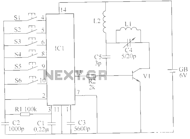
This example describes a wireless remote control switch featuring reliable operation and practical characteristics, capable of remotely controlling a 6-channel device within a 6-meter range for household electricity. The wireless remote control switch circuit consists of a wireless transmitter...