
distance measuring sensor

The ultrasonic distance measurement system operates on the principle of time-of-flight measurement, where the time taken for an ultrasonic pulse to travel to an object and back is used to calculate the distance. The speed of sound in air is approximately 343 meters per second, and thus the distance can be calculated using the formula:
Distance = (Time * Speed of Sound) / 2
The design of the ultrasonic transmitter involves careful consideration of the oscillation frequency, which must match the resonant frequency of the transducer for optimal performance. The use of a CMOS astable multivibrator allows for precise frequency control, enabling the generation of ultrasonic waves that can effectively propagate through the air.
The receiver circuit must be designed to detect weak ultrasonic signals, which requires high sensitivity amplification. The two-stage amplifier configuration ensures that even small echoes are amplified sufficiently for further processing. The rectification and smoothing stages convert the AC signal from the transducer into a usable DC voltage, which is then compared against a reference voltage to determine the presence of an echo.
For practical implementation, attention should be paid to the layout of the circuit, ensuring that components are placed to minimize noise and interference. Proper grounding and shielding techniques can enhance the performance of the system, especially in environments where external ultrasonic noise may be present. The overall design should also include considerations for power supply requirements, ensuring that the system operates reliably over its intended range.One crude method for distance measuring is by using an ultrasonic transducer. the principle is that u send a burst of ultrasonic wave in the direction of the object and it is reflected back to the ultrasonic receiver. by measuring the time delay from transmission to reception, u can measure fairly accurately the distance of the object.
the drawbacks are: note that u get a ultrasonic pair with a defined centre frequency (usually just above the audio range i. e between 30khZ and 45khz). and u may have to create the frequency using the AVR. please post the method/principle involved (if possible) because the principle of measuring propagation time of the signal is definitely ruled out as the IR signal travels at the speed of light which is too fast for even for the fastest uC to respond to. e. g. for the signal to travel a distance of say 30cm, the IR signal would take roughly 1nanosecond. If u have any doubts on their working, search for the appropriate topic on the forum ( where ur doubts ma have been raised by some other member and the solution already suggested) and if ur doubts are still not cleared, post it on the forum on the appropriate section by starting a new thread.
the pinout of utrasonic transducers and their specifications vary with the manufacturer and should be provided by the vendor/manufacturer along with the sensor itself. So when u enquire about the sensor pair, be sure to get the specifications of the sensor. I myself had done a project on ultrasonic distance measuring/object counting and used a ultrasonic transducer pair operating at 33khz interfaced to a 8085 uP(8051 core uCs were a rarity in those days as the technology itself had just entered the indian market at that time!
the only manufacturer was intel with the 80c31 and the 87c51 series. ). Had purchased it in mumbai itself from a company called pulse echo systems and the company had sent all the details but that was a long time ago ( more than 10 years back. even the firm does not seem to exist anymore!). u can generate a square wave of 40khz at any port pin using the AVR internal timer (use the PWM principle with a fixed 50% duty cycle.
). Now, amplify the voltage level of the square wave according to the data sheet before feeding it to the transmitter. ( if i remember correctly, the sensor can operate at more than 30V DC). this is neccesary because the range of the sound wave is dependent on the energy u transfer to it which is directly proportional to the operating voltage.
u can achieve it using a simple NPN power transistor. now the principle as i explained earlier is that u have to generate a limited train of pulses at that frequency (10~20 pulses is sufficient). simultaneously, start a internal timer inside the AVR. the next step would be to stop the timer as soon as u receive the first pulse from the receiver. the timer value would be directly proportional to the total distance travelled by the wave. Ultrasonic Transmitter is based on a 4011 quad 2-input NAND gate. Two of the gates, IC1a and IC1b, are used as a conventional CMOS Astable circuit whose oscillation frequency is set by capacitor C1, resistors R6 and R7, plus preset VR2, which adjusts the frequency.
Gates IC1c and IC1d buffer the outputs from IC1a and IC1b and drive the ultrasonic transmitter transducer, X1, in push-pull mode. In the Receiver circuit, ultrasonic echo signal is received by transducer X2. It is first amplified by the 2-stage amplifier based on transistors TR1 and TR2. The output from TR2 is rectified by diode D1 and smoothed by capacitor C4. The result is a voltage level at inverting terminal of IC2 which varies between 1 ·4V and 2 ·7V when X2 is not receiving ultrasound echoes, but falls to 1 ·2V when a strong enough echo from an object is detected.
The rectified signal goes to op amp comparator IC2`s inverting input, pin 2. The signal is compared with a reference voltage set by preset VR3, and applied 🔗 External reference
Related Circuits
This circuit is utilized for proximity detection and touch-controlled switching. When a finger approaches the sensor, it generates a capacitance to ground with a value ranging from 30 to 100 pF. Components involved include a resistor, capacitor, diode, and...
This two-part article explains the utilization of a simple voltage divider circuit incorporating a thermistor to obtain high-accuracy temperature readings across a wide range of measurements. The first part focuses on the circuit design and explores various methods for...
This is an ultrasonic motion detector circuit with high movement sensitivity. It can detect even minor air movements, such as hot air rising or wind blowing, when the trimpot is adjusted to a sensitive position. The transmitter emits a...
This circuit is one of the most basic and popular sensor modules. In electronics, this sensor is analogous to human visual senses and can be used. The described sensor module serves as a fundamental component in various electronic applications, emulating...
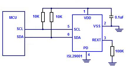
The Intersil ISL29001 is a digital light sensor designed to measure light intensity and easily interface with a microcontroller. The Intersil ISL29001 is a highly integrated digital light sensor that operates using a photodiode and an analog-to-digital converter (ADC) to...
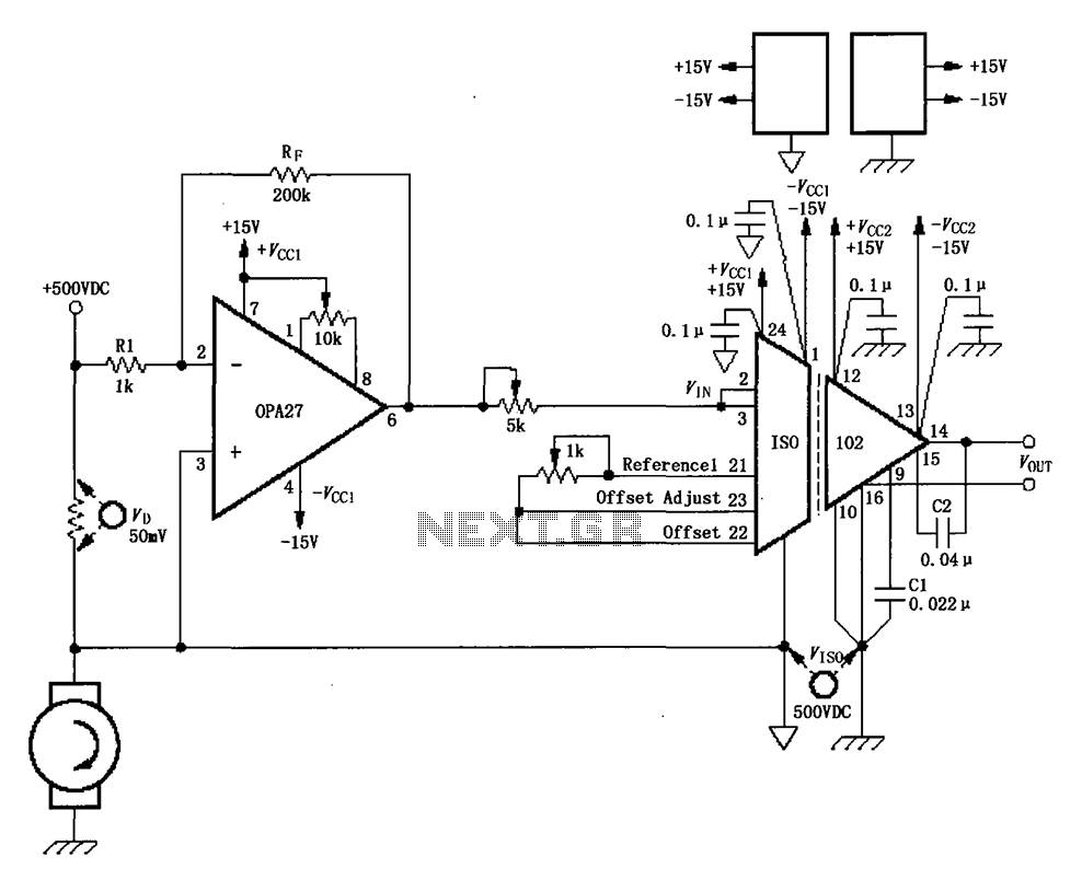
The circuit depicted in the figure consists of an ISO102 and OPA27 for measuring DC current at a voltage of +500V. It is configured between a +500V DC voltage source and a sampling resistor that is in series with...