
LM339D Simple Capacitive Touch Sensor

The proximity detection circuit operates by measuring variations in capacitance caused by the presence of nearby objects, such as a human finger. The LM339D, which is a quad comparator, plays a crucial role in processing the signals generated by the sensor. The capacitive sensing mechanism works by detecting changes in the capacitance between the sensor and the ground, which occurs when a conductive object, like a finger, comes close.
In this configuration, the capacitor is typically connected in parallel with the sensor to stabilize the readings and filter out noise. The resistor is used to set the sensitivity of the circuit; it can be adjusted to change the threshold at which the comparator triggers. The diode is included to protect the circuit from voltage spikes that may occur during operation.
When the capacitance exceeds a predefined threshold, the LM339D outputs a high signal, which can be used to drive a load or activate another circuit. This makes the design suitable for applications such as touch-sensitive switches, where the user can control devices by simply bringing their finger close to the sensor without making physical contact. Overall, this circuit provides an efficient and reliable method for proximity detection and touch control, leveraging the properties of capacitive sensing technology.Used for proximity detection and touch-controlled switching. for example, a finger comes close to the sensor, it creates a capacitance to Earth with a value of 30 to 100 pF. Component: Resistor, Capacitor, Diode, LM339D IC 🔗 External reference
Related Circuits
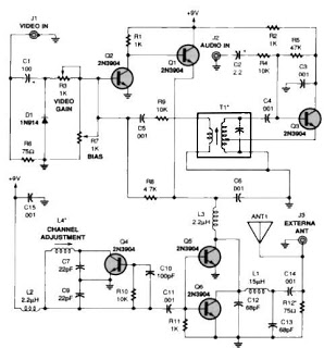
A simple TV audio-video transmitter circuit can be constructed using this schematic diagram. This circuit allows for the transmission of video signals from a VCR or other devices to a TV without the need for cables. The video signals...
This schematic diagram illustrates a 555 IC water level sensor and detector alarm circuit. The circuit is powered by the emitter current of the BC109C transistor. The 555 timer operates as an astable oscillator in this configuration. Under dry...
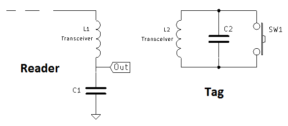
A coil of approximately 1 mH is utilized for both sides of the circuit. Given a chosen frequency of 125 kHz, the required capacitor value is calculated to be 1.62 nF, with a standard value of 1.5 nF selected....
The Current Sensor Board features an Atmel AVR AT90S8535 microcontroller operating at 8 MHz. It samples six ADC current inputs and utilizes the remaining two ADC inputs for controlling an integrating charge counter. The processed results are encapsulated into...
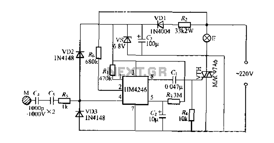
Development and production of a specialized touch dimmer integrated circuit. This circuit features four lighting functions: dark, medium, light, and a touch-sensitive trigger on all four sides. It has low harmonic radiation emission, high touch sensitivity, and stability. It...
The ultra-simple tilt sensor alarm circuit can be constructed using readily available, inexpensive components. This circuit is based entirely on transistor technology. The homemade tilt sensor consists of a small glass or plastic bottle with two metal needles inserted...