
diy 100 phr 803t violet laser

The tutorial aims to provide guidance on a specific topic, leveraging the creator's previous experience in producing instructional content. The focus will likely be on delivering clear and concise information, ensuring that the audience can easily follow along.
In the context of electronics, a schematic diagram could be presented to illustrate a particular circuit design. This schematic would typically include various components such as resistors, capacitors, diodes, and integrated circuits, all represented with standardized symbols. Each component would be connected by lines that indicate the electrical connections between them.
For example, a simple LED circuit schematic could be described. This circuit would include a power supply, an LED, and a current-limiting resistor. The power supply would be represented by a voltage source symbol, while the LED would be depicted with its specific symbol, showing the anode and cathode. The resistor would be indicated by its standard symbol, and the value of the resistor would be noted alongside it to ensure proper current flow through the LED.
The schematic would also demonstrate the flow of current, with arrows indicating the direction from the positive terminal of the power supply, through the resistor, and into the LED, before returning to the negative terminal of the power supply. This visual representation would be essential for understanding the circuit's operation and for troubleshooting any issues that may arise during assembly or testing.
Overall, the tutorial aims to enhance the audience's understanding of the topic through well-structured content and clear visual aids, ensuring that learners can effectively grasp the concepts being presented.Hey everyone! This is my first tutorial, but I do have experience with other tutorial making! So I will be fine. As a side note, my camera is not.. 🔗 External reference
Related Circuits
The schematic of the power supply is illustrated below. It operates using standard household power of 120VAC at a frequency of 50/60Hz, with an adjustable output that can reach up to 25kV or higher. The power supply circuit is designed...
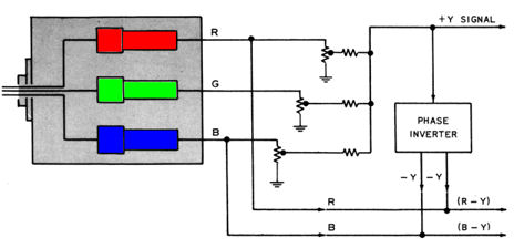
If you have not already read the CT-100 restoration article, it is recommended to start there. It chronicles the discovery of a CT-100 and its restoration to working condition. This article discusses the internal components of the CT-100. After...
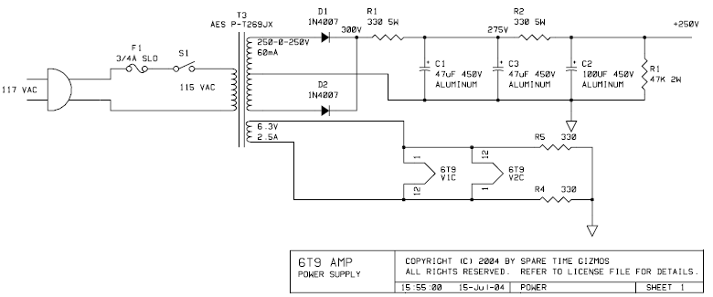
The PCB for this amplifier can be purchased from Spare Time Gizmos for $16 US. In a single afternoon, the entire board can be assembled and placed into a chassis of choice. The value and type of components are...
The development of the entire system necessitated a thorough identification of all processes related to the laser controller. The initial diagram outlines the primary physical components utilized in the CNC laser system. The setup includes a power supply, a...
There is a significant amount of vintage amateur equipment that many enthusiasts have chosen to restore and rejuvenate. Although many early amateur transceivers operate effectively, they typically lack a digital readout and depend on analog dials for tuning. The...
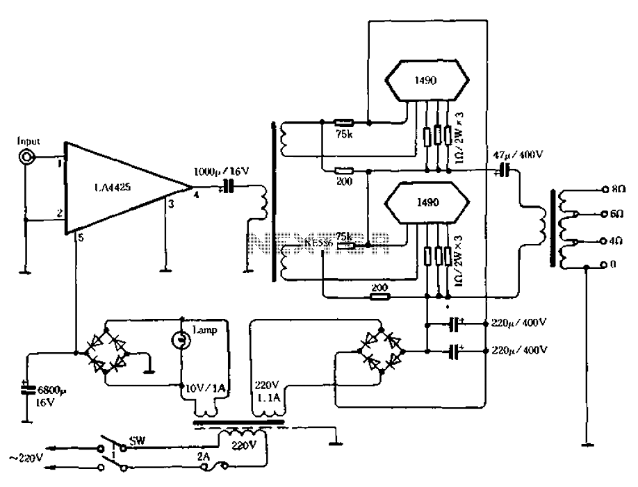
As illustrated in Figure 3-30, the IC LA4425 power amplifier stage is utilized alongside a pair of power module 1490 configured for push-pull output. This setup functions as an impedance converter, enabling the system to deliver 100 watts of...