
100W + 100W power amplifier

The circuit design employing the LA4425 power amplifier is optimized for high-efficiency audio performance in a compact form factor. The push-pull configuration of the power module 1490 enhances the output by allowing both halves of the waveform to be amplified, which is essential for driving speakers effectively. The ability to support multiple speaker impedances (4, 6, or 8 ohms) ensures versatility in application, making this amplifier suitable for various audio setups.
The schematic includes essential components such as capacitors and resistors that are strategically placed to filter and stabilize the power supply, ensuring clean audio output. The three integrated circuits play critical roles in signal processing, feedback control, and output stage driving, contributing to the overall fidelity and performance of the amplifier. The bridge rectifiers convert AC to DC, providing the necessary power to the amplifier modules, while the transformers are responsible for voltage regulation, ensuring that the amplifier operates efficiently under varying load conditions.
This circuit's simplicity, with only five capacitors and ten resistors, reduces potential points of failure and simplifies troubleshooting and maintenance. The design is particularly appealing to hobbyists and audio enthusiasts who appreciate the ease of assembly and the high-quality sound output it can deliver. The overall configuration promotes a user-friendly experience, enabling quick assembly and reliable operation, aligning with the needs of both novice and experienced builders in the audio electronics community. As shown in Figure 3-30 to promote the use of IC LA4425 stage power amplifier, a pair of power module 1490 as a push-pull output, since the impedance converter, whether the spe aker is 4fl, 6fl or 8n, are able to obtain lOow output power, the figure is depicted in a channel stereo system circuit, the other channel 6 with this exact structure of this circuit is characterized by ten. Sub-compact, the composition of the various parts of a glance, as long as the correct welding Needless to commissioning into operation...
Since the whole machine RC components. Not much, only a total of five capacitors, resistors 10, plus three IC, two blocks bridge rectifiers and three transformers, thus collecting element is not himself or herself, save when welding province, popular audio hobby favor.
Related Circuits
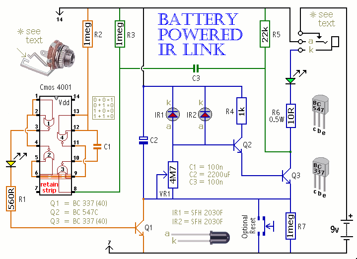
This is a battery-powered infrared (IR) link that can be utilized in multiple rooms. The standby current is exceptionally low, resulting in excellent battery life. The circuit is designed to shut down when faced with extraneous IR radiation, effectively...
The following schematic illustrates a 5.8W stereo power amplifier utilizing the Samsung IC KA2211. Each channel delivers a power output of 5.8W, resulting in a maximum combined output of 2 x 5.8W. The KA2211 is a dual audio power...
This is a non-contact power regulator circuit designed for a light load. By adjusting a 150kΩ potentiometer, phase shift can be achieved, and a trigger voltage is applied to the gate of a bidirectional thyristor through a bidirectional trigger...
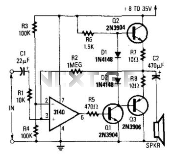
A CA3140 operational amplifier drives a complementary output stage consisting of transistors Q1, Q2, and Q3. The output power is influenced by the supply voltage and the thermal dissipation limits of transistors Q2 and Q3. Under optimal conditions, the...
This is a simple circuit which I built to one of my audio amplifier projects to control the speaker output relay. The purpose of this circuit is to control the relay which turns on the speaker output relay in...
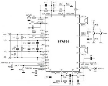
This is a stereo amplifier circuit diagram. The amplifier will produce stereo output channels with a power audio output that can reach up to 70W for each channel. The amplifier is built using the STA550 chip from STMicroelectronics. It...