
DIY 2 Layer Boards Circuit

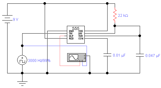
The circuit design incorporates two distinct timing mechanisms that work in tandem to control the flow of data to the shift registers. The first 555 timer serves as a primary clock generator, providing a stable, periodic signal that dictates the timing for data shifting. The configuration of two 10k ohm resistors and a 47µF capacitor establishes a time constant that results in a one-second pulse width, effectively creating a 1 Hz clock signal. This signal is crucial for the operation of the 74LS164 shift registers, allowing them to process incoming data at regular intervals.
The second 555 timer operates as a variable frequency generator, offering flexibility in the data input rate. The combination of a 1k ohm resistor, a 100µF capacitor, and the 100k ohm trimpot allows for fine-tuning of the output frequency. By adjusting the trimpot, the output frequency can be varied from 14 Hz (when the trimpot is at 100k ohms) to as low as 0.1 Hz (when the trimpot is at 0 ohms). This feature enables dynamic control over the data input rate to the shift registers, allowing for various operational scenarios.
The interaction between the two clocks is essential for the functionality of the circuit. The slower clock, dictated by the first 555 timer, ensures that data is shifted into the shift registers at a controlled rate. The faster clock, influenced by the second 555 timer, determines the timing of the data input. In cases where the slower clock exceeds the frequency of the faster clock, the data input will remain high, effectively saturating the shift registers with a constant high signal. This design illustrates the importance of timing in digital circuits, where precise control over data flow can significantly impact overall performance and functionality.For the 2 layer board schematic, we`ll use 6 core IC`s: 4 74LS164`s and 2 555 Timers. The schematic will be built using Eagle Layout Editor since all the parts I need exist in their library. The final schematic can be seen below, click on the picture for the full view. Two 555 timers are used in this circuit. The first 555 timer uses two 10k © re sistors and a 47uF capacitor, which creates an output signal that alternates between +0v and +5v every second. This clock signal will therefore shift in data to the 74LS164`s 1 bit every 1 second. The second 555 timer output signal will be fed into the data input of the 74LS164. It uses one 1k © resistor, a 100uF capacitor and a 100k © trimpot (variable resistor). When the trimpot is varied from 100k © to 0 ©, the 555 timer output frequency changes from 14 Hz to 0.
1 Hz. These shift registers will receive data input from the slower clock, which is input whenever the faster clock transitions from +0v to +5v. This means the data input will be constant since the two clocks work off of one another. Only when the trimpot is changed will the data input change, as this makes the faster clock speed up or slow down.
If the slow clock ever becomes faster than the fast clock, the digital data input will always be seen as 1. 🔗 External reference
Related Circuits
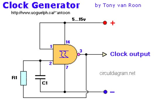
The following diagram is the clock generator circuit diagram built using NAND gate logic integrated circuits (ICs). The circuit can utilize either the IC 7400, which is a TTL type, or the IC 4011, which is a CMOS type....
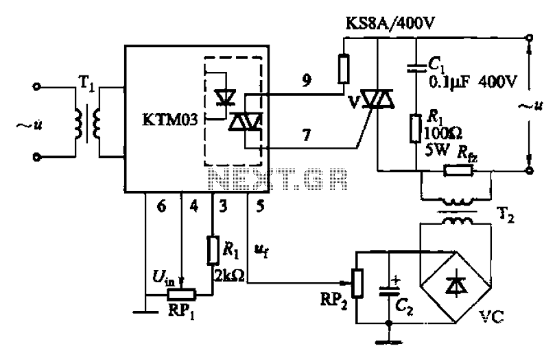
An adjustment potentiometer (RP) is utilized to set the voltage across the load resistor (Rfz) to a predetermined value. The real-time closed-loop control is achieved through the potentiometer (RPz). Open-loop control is functional as long as the feedback voltage...
The standard assumption is that the phase shift sections operate independently. According to the equation provided, the loop phase shift reaches -180 degrees when the phase shift of each section is 60 degrees. This condition is met when ω...
A continuously running cooling fan can be a significant nuisance and is not essential for most instruments. The 12V smart fan control presented here allows the fan to operate only when necessary. The 12V smart fan control circuit is designed...
This circuit is designed to dim lights with a maximum capacity of approximately 350 watts. It employs a standard TRIAC circuit configuration, which has been observed to generate minimal heat during operation. It is important to note that this...
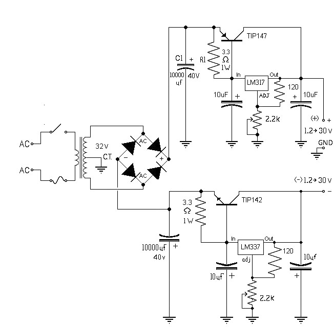
The 10A variable power supply circuit is symmetrical and can provide a symmetrical output voltage ranging from ±1.2 volts to ±30 volts DC, with a maximum current of 10A. This circuit utilizes symmetrical variable voltage regulators LM317 and LM337,...