
Phase shift oscillator circuit

The described circuit involves an operational amplifier configured for oscillation, specifically utilizing phase shift networks. The architecture typically consists of multiple RC (resistor-capacitor) sections that contribute to the overall phase shift necessary for sustained oscillation. The assumption of independence among these sections is crucial; if they were to interact, the phase shift would not achieve the required -180 degrees at the designated frequency.
In this configuration, the operational amplifier's gain must be precisely calculated to ensure that it meets the necessary conditions for oscillation. The theoretical gain of 8 is derived from the requirement that the total feedback loop gain equals one at the point of oscillation initiation. However, practical applications often necessitate a higher gain of approximately 32.4 to overcome losses and achieve stable oscillation.
The frequency of oscillation is determined by the values of the resistors and capacitors in the RC sections. The theoretical frequency of 2.76 kHz is based on ideal component values, while the practical frequency of 3.78 kHz reflects real-world conditions, including component tolerances and loading effects. The lack of buffering in the RC sections leads to loading effects that can alter the expected phase shift and gain, resulting in discrepancies between theoretical and practical outcomes.
This circuit design demonstrates improved performance characteristics, particularly in terms of distortion, when compared to traditional Wien bridge oscillators. The phase shift network's design and the operational amplifier's configuration play a critical role in achieving the desired oscillation characteristics while minimizing distortion, making it a valuable design for various electronic applications.The normal assumption is that the phase shift sections are independent of each other. Then using above Equation the loop phase shift is –1800, when the phase shift of each section is 600. This occurs when ω=2πf = 1.732/RC because the tangent of 600 = 1.732. The magnitude of β at this point is (1/2)3. So the gain, A, must be equal to 8 for the system gain to be equal to one. Therefore theoretical gain of op-amp = 8 The practical gain to start an oscillation = 32.4 The practical gain to keep oscillation = 31.6 Theoretical frequency = 2.76 Khz Practical frequency = 3.78 Khz The main reason for this is RC sections are not buffered. That is they load each other. Also the tolerance of the values of components can vary the results. But still there is a remarkable reduction in distortion comparing to the wein bridge oscillator. 🔗 External reference
Related Circuits
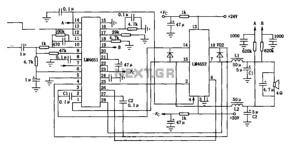
Figure (a) illustrates a 170W output amplifier circuit designed for a 4-ohm load. The LM4651 is a class D amplifier presented in a 28-pin DIP package, with its internal equivalent circuit depicted in Figure (c). The 170W output amplifier circuit...
Hobby servos convert DMX signals into mechanical motion. Typically, hobby servos require a pulse with a variable width ranging from 1 to 2 milliseconds, with 1.5 milliseconds representing the center position. The schematic below illustrates a simple voltage-to-pulse-width circuit....
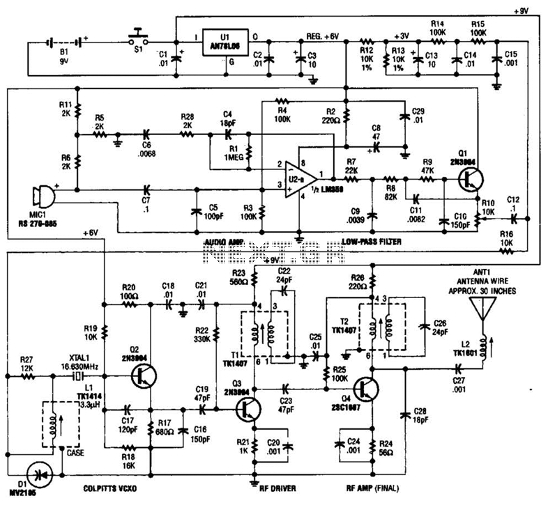
This tracking transmitter consists of four distinct subassemblies: a free-running multivibrator, a transmit switch, an audio-tone generator, and an FM transmitter. The multivibrator, which produces a pulse width with a pulse separation of 1500 ms, is built around Q1...

This is a circuit design for a doorbell that produces a bird-like sound. The circuit is controlled by an NPN transistor. The operation of the circuit begins when P1 is set to an experimental value, starting with approximately 220...
Some relays will become warm if they remain energized for some time. The circuit shown here will actuate the relay as before but then reduce the hold current through the relay coil by about 50%, thus considerably reducing the...
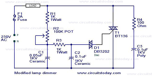
This is a modification of the Simple Lamp Dimmer/Fan Regulator circuit that was previously posted. The operation of the circuit remains the same as the original; however, it now includes a snubber circuit composed of resistor R4 and capacitor...