
DIY Audio Function Generator Part 1

The project described appears to focus on creating electronic circuits that can be completed within a few hours, emphasizing practical learning and enjoyment in the process of building. Such projects typically involve basic components such as resistors, capacitors, transistors, and microcontrollers.
To create a more substantial project, one could consider developing a simple microcontroller-based system, such as a temperature monitoring device. This project could utilize an Arduino or a similar microcontroller platform, which is ideal for rapid prototyping and learning.
The schematic for this temperature monitoring device would include the following components:
1. **Microcontroller**: An Arduino Uno or Nano, which serves as the central processing unit for the project.
2. **Temperature Sensor**: A digital sensor like the DS18B20 or an analog sensor like the LM35, which will measure the ambient temperature.
3. **Power Supply**: A USB power source or a battery pack to provide the necessary voltage to the microcontroller and sensors.
4. **Display Module**: An LCD or OLED display can be integrated to visualize the temperature readings.
5. **Resistors and Capacitors**: These passive components may be used for pull-up or pull-down configurations, as well as for noise filtering in the circuit.
6. **Breadboard or PCB**: For prototyping, a breadboard can be used to connect all components without soldering. For a more permanent solution, a printed circuit board (PCB) can be designed.
The circuit connections would involve linking the temperature sensor to the appropriate pins on the microcontroller, ensuring that any necessary resistors are placed in accordance with the sensor's specifications. The display module would also be connected to the microcontroller, allowing it to output the temperature readings for user visibility.
Programming the microcontroller would involve writing a simple code that initializes the sensor, reads the temperature data, and then outputs this data to the display at regular intervals. This project not only serves as a practical application of electronics principles but also enhances programming skills through the integration of hardware and software.
Overall, this type of project provides a foundation for more complex systems and can be expanded with additional features such as data logging, wireless communication, or integration with IoT platforms for remote monitoring.Most of my Blog posts involve short 3-4 hour projects/hacks that I just build up for learning and fun. I thought it was time to develop something a bit mo.. 🔗 External reference
Related Circuits
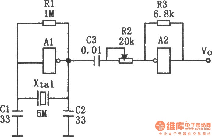
The sine wave generator composed of an inverter is illustrated in the chart. This circuit can produce a high-stability sine wave at frequencies exceeding a few megahertz. In the diagram, A1 and the crystal oscillator create an oscillating circuit,...

The TS2418 is a monolithic integrated circuit telephone tone ringer that utilizes a bridge diode. When paired with an appropriate transducer, it serves as a replacement for traditional electromechanical bells. This device is compatible with either a piezo transducer...
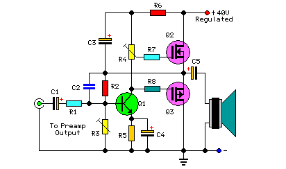
This project includes a preamplifier, tone controls, a regulated DC power supply, and delivers 18 watts into an 8-ohm load and 30 watts into a 4-ohm load. The circuit design comprises several key components that work together to create...

You need to connect pins 1 and 13 of the 4053 to the virtual ground rail (top of C4), not the circuit's 0V rail. The CD4053 is a triple 2-channel analog multiplexer/demultiplexer integrated circuit, widely used for routing analog...
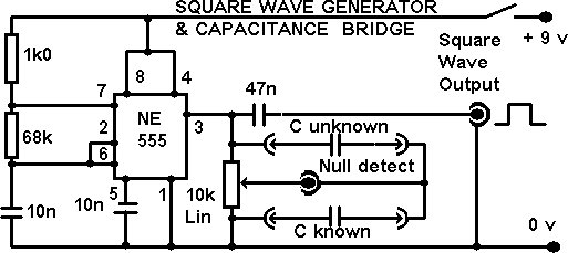
This project integrates multiple features into a compact unit. The core driver is based on an NE555 square wave generator. During development, the idea of building a square wave generator using discrete components was considered, but experiments revealed that...

In the monostable mode, the resistor can be replaced by a constant current source to provide a linear ramp voltage. The capacitor still charges from 0 to 2/3 Vcc. In a monostable multivibrator configuration, the circuit typically consists of a...