
Sine wave generator composed of inverter

The sine wave generator utilizes an inverter configuration to achieve high-frequency oscillation. The core of the circuit is formed by operational amplifier A1, which is configured as a linear amplifier. This amplifier is critical for maintaining the integrity and stability of the sine wave output. The crystal oscillator provides a precise frequency reference, ensuring that the oscillation remains consistent and accurate.
The output from A1 is a raw sine wave signal, which may exhibit some distortion due to the nonlinear characteristics of the inverter. To mitigate this, buffer A2 is employed. This buffer serves to isolate the output of A1 from any load effects, allowing for a clean sine wave signal to be produced. The buffer also increases the output drive capability, enabling the circuit to drive loads without significant degradation of the waveform.
The overall design of the sine wave generator circuit is optimized for high-frequency applications, typically in the range of several megahertz. The choice of components, particularly the operational amplifier and the crystal oscillator, is crucial for achieving the desired performance specifications. Proper power supply decoupling and layout considerations are also essential to minimize noise and ensure stable operation.
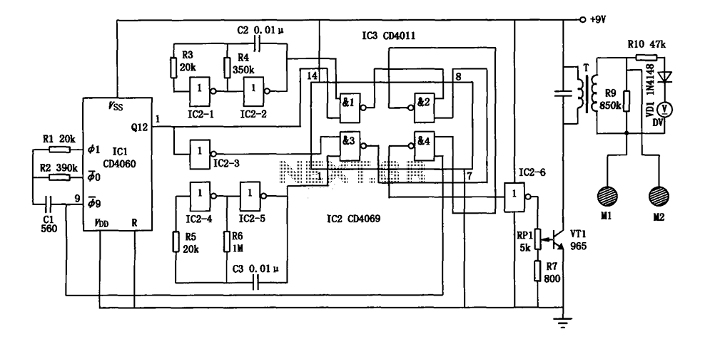
In summary, this sine wave generator circuit is a reliable solution for applications requiring high-frequency sine wave signals, with a focus on stability and low distortion.The sine wave generator composed of inverter is shown as the chart. The circuit could get high stable sine wave in more than a few MHz. In the figure, A1 and the crystal oscillator form a oscillating circuit, the output of A1 becomes sine wave signal after passing the buffer A2. In the circuit, A1 is linear amplifier, the whole circuit is in amplifying state.. 🔗 External reference
Related Circuits
This is a circuit that generates white noise, rolled-off to drive earphones or a small speaker. White noise creates is a "rushing" sound, which sounds something like air rushing by your ear(s). White noise would be flat with frequency,...
The electronic bio wave therapy instrument circuit is designed to generate a variety of complex frequency electrical signals. These signals can enhance the absorption of medication and provide direct therapeutic effects on specific body points. The electronic bio wave therapy...

This design aims to restore the classic style of telephones that utilized a pair of gongs to signal an incoming call, evoking a sense of nostalgia with the familiar sound of ringing bells. Presented here is a "Telephone Ring...
Square wave generators are typically based on symmetrical multivibrators using bipolar transistors of the same structure, along with two frequency-determining networks. However, a simpler oscillator can be constructed with two transistors of different structures (refer to figure 1) utilizing...
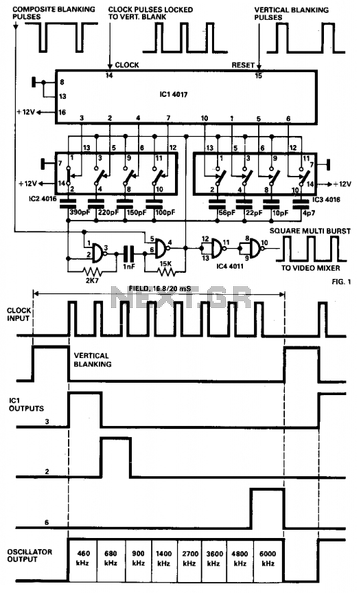
The generator described is designed for generating multiburst square waveforms and can be utilized to characterize the response of television monitor amplifiers. The circuit functions as an RC oscillator using NAND gates (IC4-4011), with the capacitor C periodically altered...
With the increase in the variety of modern electrical equipment for vehicles and the rise in power levels, there is a growing demand for different types of power supplies, including AC and DC sources. The power system needs to...