
DIY Binary Clock with Arduino

To build a binary clock using an Arduino, the circuit design incorporates multiple components, including resistors, LEDs, and push-buttons, which play crucial roles in the functionality of the clock. The primary elements involved in the assembly include:
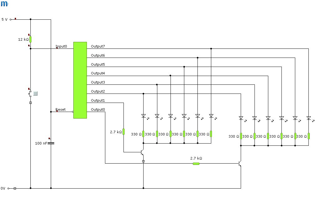
1. **LEDs and Resistors**: The LEDs are arranged in a binary format to represent the time, with each LED corresponding to a specific binary digit. The resistors are used to limit the current flowing through the LEDs to prevent damage. Each LED's anode (longer leg) is connected to an Arduino output pin (from pin 1 to pin 13), while the cathode (shorter leg) connects to ground.
2. **Push-Buttons for Time Adjustment**: The time-setting mechanism relies on two push-buttons connected to analog pins. These buttons allow the user to increment the hour and minute values. Specifically, one button is connected to analog input pin 0 for hour adjustments, and the other is connected to analog input pin 5 for minute adjustments. This configuration ensures that the clock can be easily set by the user.
3. **ON/OFF Button**: An additional button connected to digital input pin 0 serves to turn the LEDs ON or OFF. This feature is essential for conserving power when the clock is not in use.
4. **Resistor Configuration**: Each button's circuit includes a 2.2k Ohm resistor connected to the 5V output. This resistor is essential for creating a pull-up configuration, ensuring that the input pin reads a high signal when the button is not pressed and a low signal when it is. The other leg of the button is connected to ground, completing the circuit.
In summary, the binary clock assembly involves a thoughtful arrangement of LEDs, resistors, and buttons, all controlled by an Arduino. This setup not only provides an engaging project for electronics enthusiasts but also serves as a practical demonstration of binary counting and timekeeping using basic electronic components. Proper attention to connections and component specifications is crucial for successful operation.Yesterday I was going to start watching a movie, when me and my friendpedrodecided to give up on the movie and build a binary clock. After sometime thinking on how to program it, we made it. It works beautifully, so I decided to show here how I`ve done. It may not be the easiest way to make it work, but that`s what we`ve done. To assemble the circ uit, you will need to connect first the resistors and leds. To do it, just hook up leds + resistor from the pin 1 to 13. Remember that the bigger leg of the led is positive, and need to be connected to arduino output pin, and the other leg should be on the ground. For connecting the buttons, I`ve used one digital input and two analog inputs. To set change the hour/minute, you will need to use two push-buttons. And they need to be connected to the analog input pin 0 and 5. And to turn leds ON/OFF I`ve used a normal button that is connected to digital input pin 0. To make it work, you need use one leg of the buttons on a 2. 2K Ohm resistor connected to the 5V output together with the analog/digital input, and the other leg going to the ground, something like this:
🔗 External reference
Related Circuits
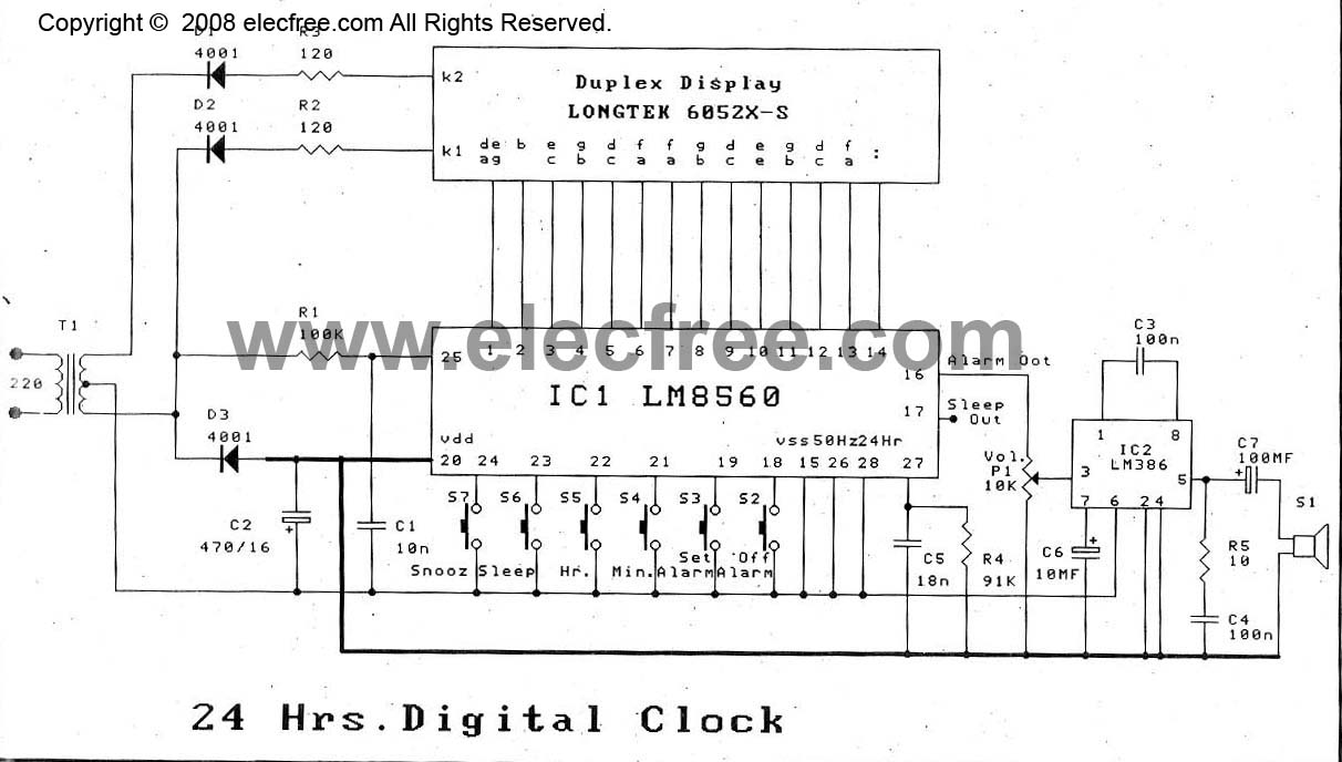
The digital time clock circuit is of great interest to electronic amateurs. The most popular clock ICs include the LM8361 and MM5387. Unfortunately, these ICs... The digital time clock circuit serves as an essential component for various electronic applications, providing...
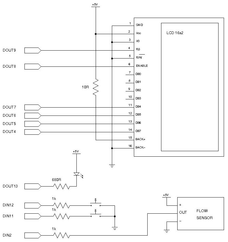
Measuring the consumption of a resource that has units by volume can be more challenging than it appears. Resources such as water, gas, and electricity are typically measured using gauges that determine either the instantaneous flow rate or the...
A series of digital clocks with LED outputs were developed for the Electronics in Schools Strategy (EiSS) and utilized in various courses organized by SETPOINT (now STEMPOINT) Devon & Cornwall for secondary school educators in the southwest. The initial...
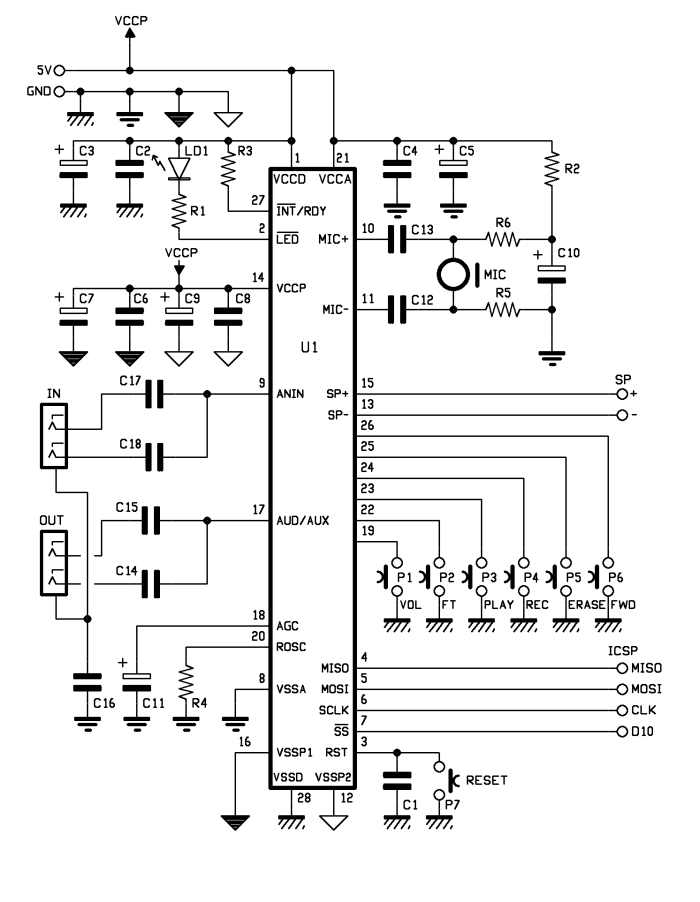
The aim of this project is to create an Arduino voice shield that facilitates numerous voice-related applications, primarily utilizing an integrated ISD1790PY chip. This voice and text-to-speech (TTS) functionality can be beneficial for integrating voice messages into alarm systems,...
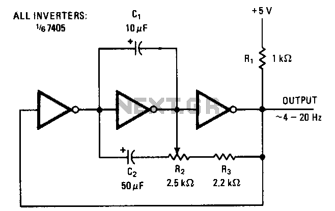
The symmetry of the square-wave output is maintained by connecting the right side of resistor R2 through resistor R3 to the output of the third amplifier stage. This configuration alters the charging current to the capacitors in proportion to...
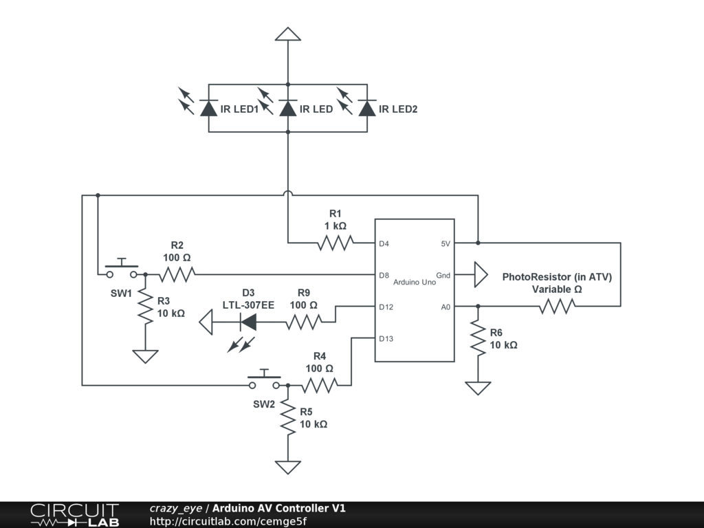
Arduino Event-Driven Universal AV Remote May 1st, 2013. Turn everything on with Airplay. The project involves the development of an Arduino-based universal remote control designed to manage various audio-visual (AV) components through an event-driven architecture. This remote utilizes Airplay...