
DIY Infrared Radar System

The do-it-yourself radar system utilizing the PIC18F452 microcontroller presents an engaging project for electronics enthusiasts. The PIC18F452 is a versatile microcontroller from Microchip Technology, equipped with a 14-bit instruction set architecture, 32 general-purpose I/O pins, and integrated peripherals, making it ideal for various applications, including radar systems.
The radar system operates by emitting a radio frequency signal and measuring the time it takes for the signal to reflect off an object and return to the receiver. The PIC18F452 microcontroller is programmed to control the timing and processing of the received signals, allowing it to calculate the distance to the object based on the time delay.
Key components of the radar system include an RF transmitter and receiver, which may be implemented using antennas designed for the specific frequency band of operation. The microcontroller interfaces with these components through its GPIO pins, utilizing PWM (Pulse Width Modulation) for signal generation and ADC (Analog-to-Digital Conversion) for processing the received signals.
The circuit may also include additional elements such as a display module (e.g., LCD or OLED) to visualize the distance measurements, and a power supply circuit to ensure stable operation of the microcontroller and RF components. Proper filtering and amplification circuits are essential to enhance signal clarity and reduce noise interference.
Overall, this project not only demonstrates practical applications of microcontroller programming and RF communication but also provides valuable insights into radar technology, making it a comprehensive learning experience for hobbyists and students in the field of electronics.Chris has a great article about a do-it-yourself radar system build with PIC18F452. It s a great hobby project although the schematic.. 🔗 External reference
Related Circuits
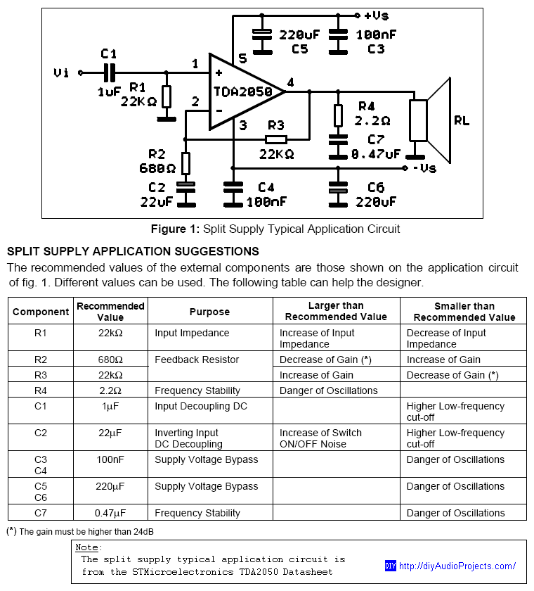
DIY TDA2050 Non-Inverting Chip Amplifier project constructed on a protoboard. The TDA2050 is a popular audio power amplifier integrated circuit designed for various audio applications. This non-inverting amplifier configuration is particularly valued for its simplicity and effectiveness in delivering high-quality...
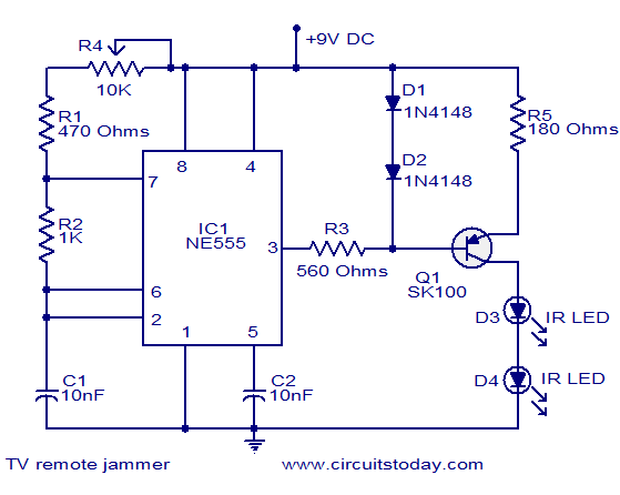
Here is the circuit diagram of simple but highly effective TV remote jammer circuit. Most of the TV remotes have 38KHz operating frequency. A flood of IR beams in the same frequency can easily confuse the TV receiver and...

The circuit utilizes the widely used Sharp IR module (the Vishay module can also be employed). The pin numbers indicated in the circuit are applicable to both the Sharp and Vishay modules. For other modules, it is advisable to...
The transmission circuit for inductive wireless headsets must be securely mounted on a wall or ceiling, limiting its outdoor usability, which is a significant disadvantage of inductive wireless headphones. In contrast, infrared wireless headsets utilize a compact infrared transmitter...
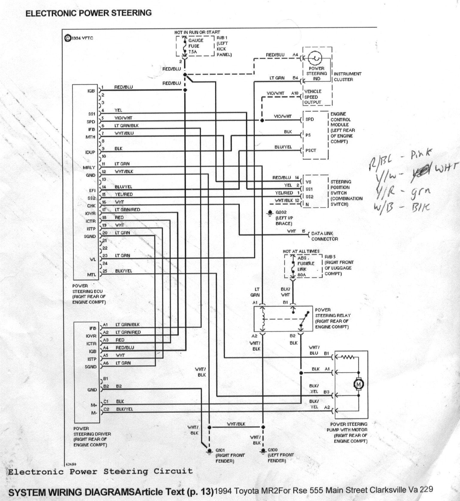
The goal was to control the MR2 power steering pump to reduce noise and power consumption, as it operates at full throttle continuously. Designing a custom motor controller was not feasible due to a lack of expertise, and off-the-shelf...

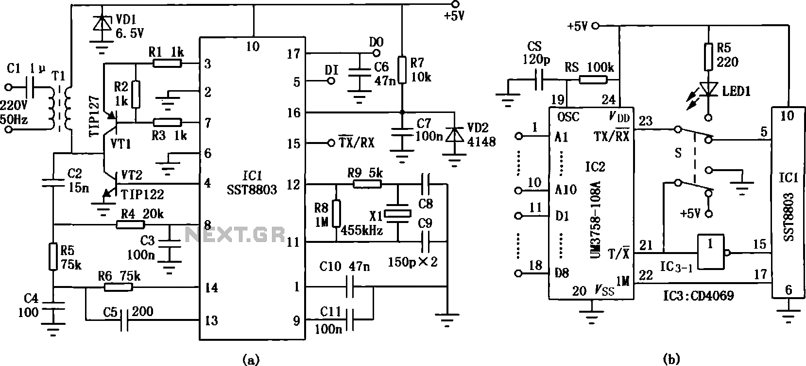
The circuit design philosophy allows for debugging without any RF instruments. Although its performance may not match that of professional equipment, it should be adequate for hobbyists, with audio-visual transmission effects comparable to general-purpose machines. The transmitter consists of...