
InfraRed Jammer with 555

The circuit operates as an astable multivibrator, utilizing the NE555 timer IC, which generates a continuous square wave output at a frequency of approximately 38 kHz. This frequency corresponds to that used by most TV remote controls, making it effective for jamming their signals. The NE555 is configured with external resistors and a potentiometer (R4) that allows for fine-tuning of the output frequency to closely match that of the target remote control.
The output from the NE555 is connected to a PNP transistor (SK100), which acts as an amplifier. The transistor is responsible for driving multiple infrared (IR) LEDs in parallel, which emit a flood of IR light at the specified frequency. This overwhelming signal interferes with the normal operation of the TV remote by saturating the IR receiver in the TV, thereby preventing it from detecting the legitimate signals from the remote.
The circuit is powered by a 9V PP3 battery, providing sufficient voltage for the NE555 and the IR LEDs. To ensure reliable operation, it is recommended to mount the NE555 IC in a holder to facilitate easy replacement if necessary. The assembly can be done on a Vero board, allowing for a compact and organized layout of components.
The adjustment of the potentiometer (R4) is crucial, as it allows the user to calibrate the frequency of the jamming signal to match that of the specific remote control being targeted. This level of customization enhances the effectiveness of the jammer, ensuring that it operates optimally against various IR remote controls operating at or near the 38 kHz frequency. Proper setup and adjustment of the circuit will yield a device capable of effectively disrupting the communication between the remote control and the TV receiver.Here is the circuit diagram of simple but highly effective TV remote jammer circuit. Most of the TV remotes have 38KHz operating frequency. A flood of IR beams in the same frequency can easily confuse the TV receiver and this is the operating principle of our jammer. The circuit is nothing but an astable multivibrator based on NE555 IC. The output of NE555 is amplified using a PNP transistor SK100 to drive the IR LEDs. Not only TV remotes, but any IR remotes operating in the 38KHz frequency region can be also jammed by using this circuit.
The circuit can be assembled on a Vero board. Use a 9V PP3 battery for powering the circuit. Mount the IC on a holder. POT R4 can be adjusted to exactly match the jammer’s frequency to the remotes frequency. This adjustment is very essential for effective jamming. 🔗 External reference
Related Circuits
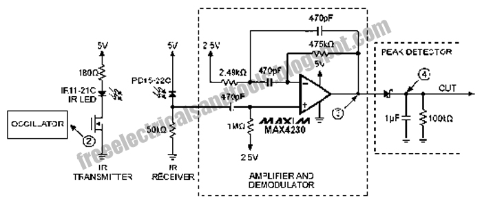
The following circuit illustrates an Infrared Proximity Sensor Circuit Diagram. This circuit is based on the MAX4230 integrated circuit. Features include a 10 kHz oscillator. The Infrared Proximity Sensor Circuit utilizing the MAX4230 integrated circuit is designed to detect the...
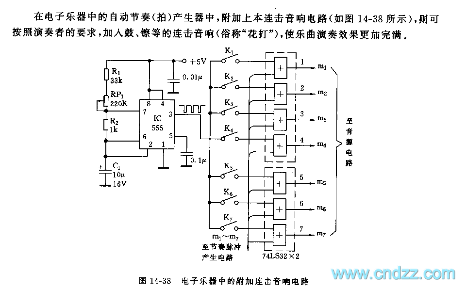
Adding this combination audio circuit, as illustrated in figure 14-38, to the automatic rhythm generator of electronic musical instruments fulfills the players' demand for incorporating drum and cymbal audio, enhancing the overall performance effect. The diagram indicates that the...
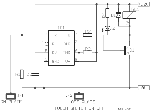
This type of sensor switch is ideal for creating touch-operated bells and buzzers in small toys, which function for a limited duration before automatically shutting off. The trigger's input impedance is very high, allowing the touch sensor switch to...
Firecrackers are typically ignited using a matchstick or a candle. It is important to move away quickly after lighting the fuse of the firecracker. This method.. Firecrackers operate on the principle of rapid combustion, which produces a loud noise and...
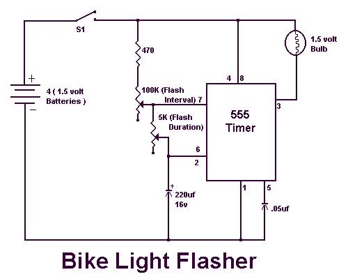
I ride my bike allot at night and sometimes I'm not sure if people can see me. This circuit will flash an incandescent light that you can purchase from Radio Shack. Adjust the VR's for your flash requirements and...
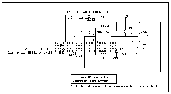
This is an IR transmitting circuit which can be used in many projects. This IR transmitter sends 40 kHz carrier under computer control. The circuit can be controlled using any TTL or RS-232C level control signal which makes the...