
Dodd Station

Dodd's 1912 station employed a Damped Wave Spark Transmitter. The radiated signal takes the form of a pulsating wave train composed of successive damped wave oscillations at a radio frequency determined by the LC of the Sending Condenser and the Helix. Damped wave refers to the phenomenon where each successive wave peak in the oscillation pulse exhibits reduced amplitude compared to the preceding peak. Ideally, this decay would produce strong RF signals capable of being received over great distances.
The damped waves are generated through a specific process. The Spark Transformer generates a high potential AC that charges the Sending Condenser as the positive voltage of the AC increases. Once the charge voltage reaches a sufficiently high level, the insulating properties of the Spark Gap break down, resulting in an arc that temporarily shorts the transformer secondary, effectively removing it from the circuit. The Sending Condenser then discharges into the Helix. At this point, the AC potential from the Spark Transformer has reached its peak and is declining toward zero, preventing further arcing at the gap. However, the Helix, charged by the positive discharge of the Sending Condenser, creates an electromagnetic field. As this field collapses, it generates a negative back-EMF that arcs the gap, recharging the Sending Condenser with reverse potential. This process repeats, with the gap arcing again and recharging the Helix to create a new electromagnetic field, which subsequently collapses, causing another arc at the gap.
This cycle of charging and discharging occurs at a higher potential and frequency than that of the spark transformer secondary, effectively disconnecting the spark transformer from the circuit temporarily. The damped wave oscillation between the Sending Condenser and the Helix repeats multiple times, with each successive peak exhibiting diminished amplitude compared to the previous one. With appropriate charge frequency and quenching (closed circuit loading), approximately 40-50 oscillations occur before the amplitude of the damped waves reduces to about 0.02 of the initial amplitude. At this point, the damped wave potential load falls below the AC charging potential from the Spark Transformer, which reaches sufficient potential on the negative voltage peak to restart the process. The damped wave production continues with each positive and negative cycle of the AC charge voltage as long as the telegraph key remains depressed. When the key is closed, a constant arc appears across the spark gap; however, a high-speed motion picture camera would reveal a rapid series of arcs that are part of the damped wave creation process.Fortunately, Dodd`s 1909 receiver has survived. It was found among the many parts that were in various boxes that I had purchased at the yard sale. The pieces were identified from the 1909 Station photo. Many of the 1909 Station parts were used in the construction of Dodd`s 1912 station. The most obvious component is the helix that changed very little in its incorporation in the 1912 station. I restored the 1909 Tuning Inductance in 2009 and it, along one of the home made detector stands and the single Kellogg earphone that Dodd is using in the photo, is now on display in the Museum. Since the inductance (and receiver) is so primitive, I have also included a copy of this photograph in the display so viewers can recognize that the components they are looking at is actually a 1909 receiver.
The Transmitter Basics - Dodd`s 1912 station uses what was called a Damped Wave Spark Transmitter. The actual radiated signal is in the form of a pulsating wave train made up successive damped wave oscillations at a radio frequency determined by the LC of the Sending Condenser and the Helix. Damped wave means that each successive wave peak in each damped wave oscillation pulse is of reduced amplitude compared to the proceeding wave peak.
An ideal decay or decrement of the damped waves would produce strong RF signals that could be copied at a great distance. The damped waves were created in the following manner. The Spark Transformer provides a high potential AC that is allowed to charge a Sending Condenser on the increasing positive voltage of the AC.
When the charge voltage reaches a high enough potential, the insulating properties of the Spark Gap break down and the gap arcs over which effectively removes the transformer secondary from the circuit by a temporary short. However, the Sending Condenser then is discharged into the Helix. At this time the charging AC potential from the Spark Transformer has passed its peak and is now heading toward zero potential - it can`t arc the gap.
However, the Helix has been charged with the positive discharge of the Sending Condenser which has created an EM field in the Helix but there is no real potential to sustain the field, so it collapses. The collapse of the Helix field creates a negative back-EMF that arcs the gap and re-charges the Sending Condenser (reverse potential, ) which then arcs the Spark Gap again and re-charges the Helix to again create the EM field which collapses, arcs the gap and again recharges the Sending Condenser (positive potential.
) This charging and discharging is all at a higher potential and a higher frequency than the secondary of the spark transformer and so dominates the use of the gap and effectively has disconnected the spark transformer from the circuit, temporarily. This damped wave oscillation between the sending condenser and the helix is repeated time after time but each successive peak is of less amplitude than the proceeding wave peak.
With the proper charge frequency and quenching (closed circuit loading) about 40-50 oscillations (depending on the RF) occur before the amplitude of the damped waves is reduced to about. 02 of the initial amplitude. At about this time the damped wave potential load is less than the AC charging potential from the Spark Transformer which has reached sufficient potential on the negative voltage peak to start the process all over again.
The damped wave production is repeated with each positive and each negative cycle of the AC charge voltage as long as the telegraph key is depressed. When the telegraph key is closed, one sees what appears to be a constant arcing across the spark gap but if you had a very high speed motion picture camera the discharge could be seen as a rapid series of arcs that are part of the process of creating damped waves.
Photo right: Showing a single damped wave pulse and its RF component. The OPEN damped wave is with no "quenching" and the oscillati 🔗 External reference
Related Circuits
The purpose of this report is to provide background and findings of our senior project. We will discuss four steps that we used to complete our final project. The four steps of our project were research and development, design,...
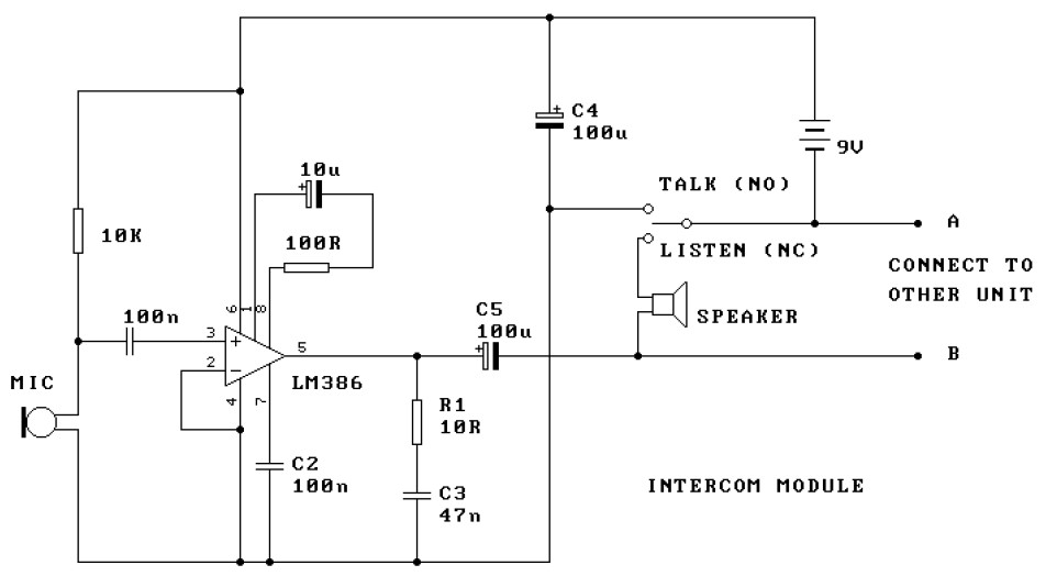
This is a two-station intercom system that operates using two wires connecting each intercom unit. Each unit is self-contained, equipped with its own battery, speaker, microphone, and amplifier circuit. An LM386 audio power amplifier is utilized, which is widely...
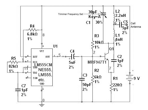
This device functions as a reversal of a radio station, sending a null signal to a selected frequency to eliminate the actual broadcast. The radio transmitter operates at a loss of 10,000W; therefore, this circuit is intended for use...
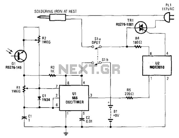
An infrared-sensitive phototransistor is employed to detect the temperature of a soldering iron. The phototransistor must be positioned to view the tip through an opaque tube to prevent interference from stray light, and it is advisable to equip the...
The mixer features two stereo phono inputs and two stereo line-level inputs, along with one stereo bonded channel. Additionally, it includes a microphone input and a stereo output with adjustable gain. The mixer is designed to facilitate audio mixing and...
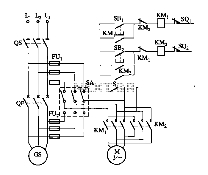
FIG M is a variable speed motor control for the opening and closing of a wicket gate. It features an electric governor. The system is activated by a power switch (SA) located on the front grid, and a toggle...