
Dodge Cummins Diesel Forum
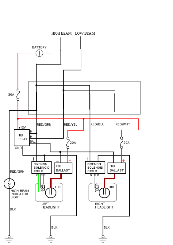
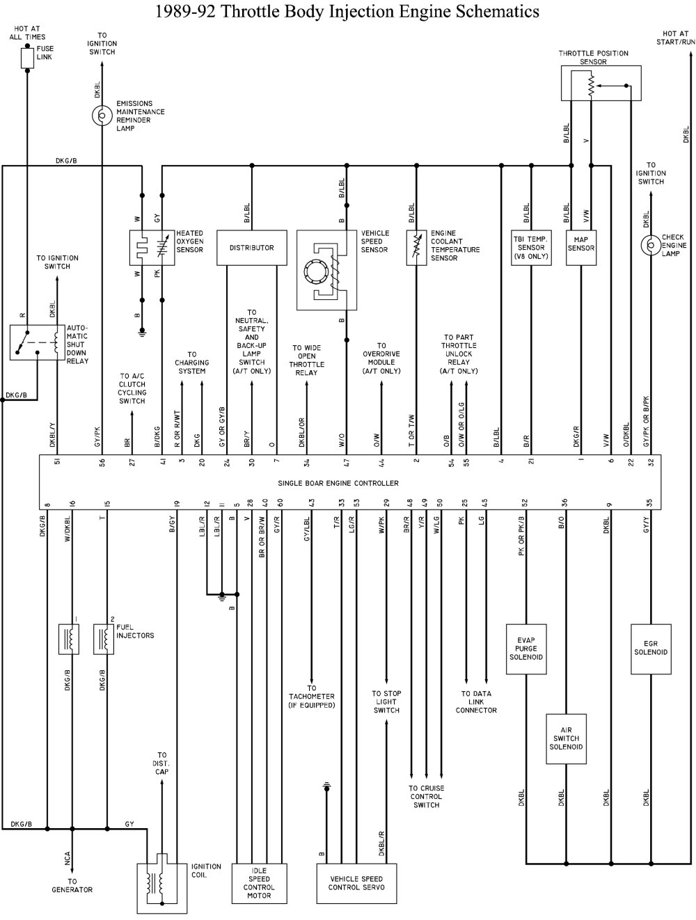
A wiring diagram serves as a visual representation of the electrical connections and layout within a vehicle, particularly for modifications or enhancements. This schematic is crucial for understanding how to integrate additional components, such as lighting, audio systems, or other electronic accessories, into the existing electrical system of a truck.
The wiring diagram typically includes details such as the color coding of wires, the location of connectors, and the specific function of each component. It may also illustrate the power sources, ground connections, and any necessary fuses or relays required for safe operation.
When creating or interpreting a wiring diagram, it is essential to follow a systematic approach. First, identify the components that will be added or modified. Next, consult the vehicle's original wiring diagram to understand the existing electrical layout. This will help to determine the best points for integration, ensuring that the new components do not interfere with the vehicle's original systems.
Additionally, it is advisable to include annotations on the diagram to clarify connections and functions. This can aid in troubleshooting and future modifications. Proper labeling of wires and connections can prevent confusion during installation and maintenance.
Safety precautions should also be highlighted in the wiring diagram, including the importance of disconnecting the battery before making any modifications and verifying that all connections are secure and insulated to prevent shorts or electrical failures.
In summary, a well-structured wiring diagram is an invaluable resource for anyone looking to enhance their truck's electrical system, providing a clear roadmap for successful installation and integration of new components.For all those who like to add stuff to there truck(thats about every body) im starting a thread JUST OF WIRING DIAGRAMs Before posting your diagram.. 🔗 External reference
Related Circuits
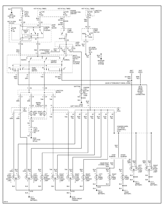
A 1997 Dodge Dakota extended cab sport owner is seeking a wiring diagram for the tail light or brake light system. To locate the wiring diagrams for the tail light and brake light systems of a 1997 Dodge Dakota extended...
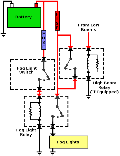
Dodge Durango Fog Light Wiring Diagram. The Dodge Durango fog light wiring diagram provides a visual representation of the electrical connections and components involved in the fog light system of the vehicle. This diagram typically includes the battery, fog light...
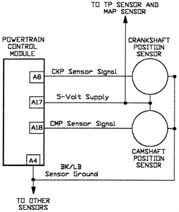
For this test, an analog (non-digital) voltmeter is required. The distributor connector must remain intact. Small paper clips should be inserted into the backside of the distributor wire harness connector to establish contact with the terminals without damaging the...
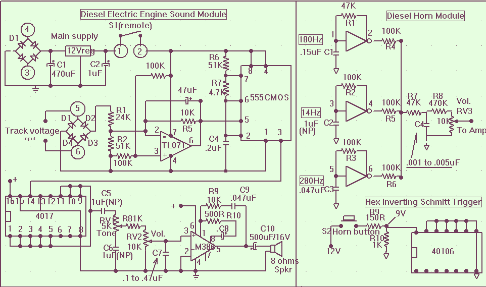
The main power supply to the system must be a regulated 12 volts DC with a minimum input from the train control AC or DC power supply of 13.5 VAC connected to pos 3 and 4 of the rectifier...
This webpage provides a narrative log and pictorial essay on maintaining a 1989 Dodge B250 Ram Van equipped with a 5.2L engine and over 136,000 miles. It includes simple graphs aggregating various data on costs. The page aims to...

This circuit is a module for a diesel and horn train system. It is constructed using a 555 timer IC and several operational amplifiers (op-amps). The circuit serves as a complete system for the horn function. The main power...
Warning: include(partials/cookie-banner.php): Failed to open stream: Permission denied in /var/www/html/nextgr/view-circuit.php on line 713
Warning: include(): Failed opening 'partials/cookie-banner.php' for inclusion (include_path='.:/usr/share/php') in /var/www/html/nextgr/view-circuit.php on line 713