
Dome Drive Schematic

Standard potentiometers typically do not support the required 360 degrees of rotation, generally offering only 270-330 degrees, with circuits limiting them further. A multiturn potentiometer is a viable option, allowing for a 10-turn setup that could provide 2.5 revolutions of the dome. However, this may be excessive for the application. The Oatley kit utilizes the M51660L device, which has limited voltage adjustment capabilities associated with the feedback potentiometer. Modifying timing resistors or capacitors on pin 3 can adjust the rotation but may adversely affect the output frequency to the H-bridge. The output signal tends to be more of an on-off type due to the low frequency, resulting in a thumping sound rather than the high-frequency whine typical of speed controllers.
The velocity feedback resistor, which connects pin 2 to pin 6, measures the voltage pulse from the motor and relays this information to the timing pin. This signal is mixed with the capacitor-generated signal, allowing the motor to decelerate as it approaches the commanded position, thereby reducing overshoot. However, in the Oatley kit, the velocity feedback resistor measures the voltage of the gate drive transistors instead of the motor itself, which may not significantly impact performance, as the switching frequency on the gate should match that of the motor. Nonetheless, this change eliminates the coasting motor velocity.
The modifications to the circuit involve several key components. The PNP-NPN H-bridge configuration is critical for managing the high current demands of the motor, providing efficient forward and reverse operation. The use of MOSFETs in the H-bridge allows for rapid switching and reduced heat generation compared to traditional designs. The choice of the M51660L device as the core controller is significant, as it influences the overall performance of the servo system.
Incorporating a multiturn potentiometer enhances the control over the dome's rotation, allowing for fine adjustments and improved responsiveness. However, careful consideration must be taken when modifying timing components, as changes can lead to instability in the output frequency that drives the H-bridge. The feedback loop, which includes the velocity feedback resistor, plays a crucial role in ensuring accurate positioning and minimizing overshoot, making it essential to maintain proper signal integrity throughout the system.
Overall, this setup requires a balance between component selection, circuit design, and feedback mechanisms to achieve the desired functionality of a large RC servo capable of precise movement and control.A couple of changes on the dead band and Pulse Stretcher resistors, and the Position feedback potentiometer has been hacked around to function as a "zero the speed" or "center your transmitter sticks". The rest is just the addition is a fairly traditional PNP-NPN H-bridge to handle the higher currents of the large motor.
So all we have to do is change it back to function as a servo and stick a potentiometer in the middle of R2 ½s dome rotation mechanism and now we have a giant RC servo. But Oatley sells a giant RC servo kit. Why not just use that instead Sure you can. And it would work no problem if you wanted R2 ½s head to rotate a maximum of about 70-90 degrees. 35-45 degrees or so each side of center. If that is ok for your needs then just purchase the K165B kit, put it together and you ½re done. . However, other than very reduced dome rotation, the old kit has a much different H-bridge design that is not as efficient as the forward reverse kit.
And unlike the forward/reverse kit you cannot add the additional Mosfet`s to be handle larger current motors or amperage. This kits H-bridge design uses a couple of very large resistors for the Mosfet gate drive, which significantly turns batteries quickly into heat.
See Figure 5. So other options What do I want the dome to do I want at least 360 degrees of rotation. Problem is that standard potentiometers don ½t turn that far. Generally somewhere between 270-330 degrees and the circuit limits them down to half of that. So we have a number of options. The easiest is a multiturn potentiometer. Generally these larger panel mount devices come in a 10-turn style where you have to turn them 10 complete revolutions to go the full swing of the resistance. Not a bad option. I connect one on R2 and now I get 2. 5 revolutions of the dome from the RC stick end to end. Well that ½s just a little too much. So now a real problem comes into play since the Oatley kit uses the M51660L device. The voltage adjustments associated with the feedback potentiometer have a significantly small differential.
Basically you almost don`t have any. The ½ole ZN409 no problem, it was designed to be tweaked. The M51660L not really. You have a few options and that includes changing timing resistor or capacitor on pin 3. This will force the internal comparator circuit to reduce or increase the rotation. However, changing this value too much adversely affects the output frequency to the H-Bridge. Which is pretty bad to start with. Which I guess I should mention the output is more of an on-off type of thing since the frequency is so low. You hear more of a thumping as the bridges switch, but at least you don ½t have that high frequency wine you normally get from speed controllers.
The other issue is with the velocity feedback resistor. This is the resistor that goes from pin 2 to pin 6. In the hobby servo world it is measuring the voltage pulse from the actual motor and sending that back to the information to the timing pin. It is then mixing that signal with the capacitor generated signal. This will in turn allow the motor to start slowing as it reaches its commanded position because it changes the RC time constant with the capacitor it is in parallel with.
This is done so the over shoot is not as great and the dead band resistor between pins 9 and 11 can be adjusted so the position can be placed within a degree with repeatability. Not so much the case with the Oatley kit as the velocity feedback resistor is now measuring the voltage of the gate drive transistors and not what the actual motor is doing.
However, since the switching frequency on the Gate should be the same as what the motor is this should not present a huge problem. Other than we now do not have the coasting motor velocity. The onl 🔗 External reference
Related Circuits
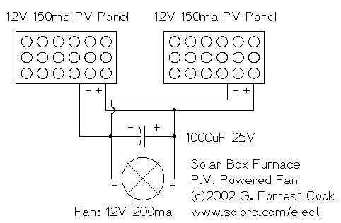
I decided to make a commercial surface mount PC board using the LED2 sensor concept. It is quite sensitive and can track to a few degrees of accuracy in bright sunlight. If a blocking shadow is used the accuracy...
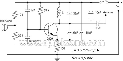
FM Wireless Microphone Schematic. In some applications, using a microphone cable can be quite challenging, necessitating the use of a cordless microphone, commonly referred to as a wireless microphone. This document presents a wireless microphone circuit schematic that utilizes...

A basic LED driver circuit consists of a 5-volt power source, a 2 kΩ potentiometer, and an LED. The LED is forward biased, with the manufacturer specifying a maximum current rating of 20 mA at a diode voltage drop...
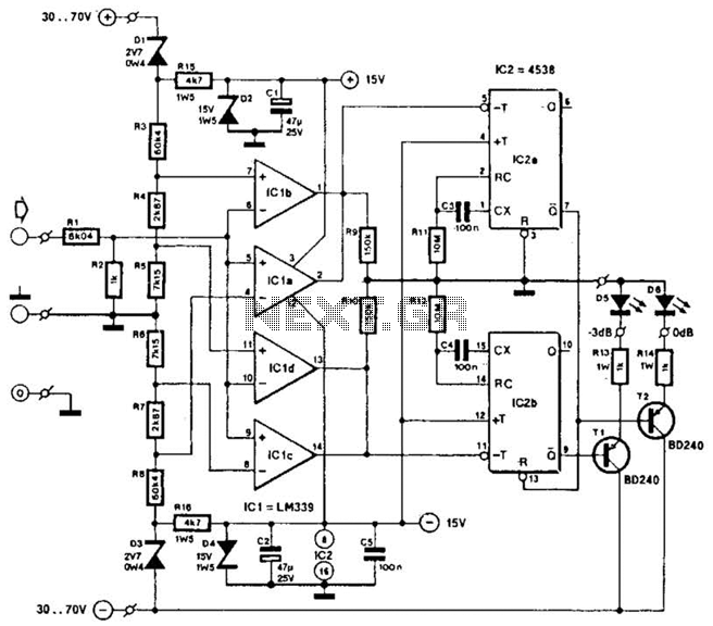
This circuit was utilized with an audio power amplifier to identify the point at which the output is -3 dB from maximum, indicated by LED D5, and at clipping, shown by LED D6. The indicator can be employed with...
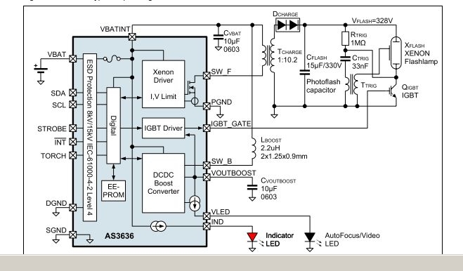
The AS3636 is a highly integrated photoflash charger that includes an IGBT driver, an inductive DC-DC boost autofocus/video LED driver, an indicator LED driver, and incorporates system-level ESD protection. The AS3636 is designed for efficient photoflash charging applications, providing a...
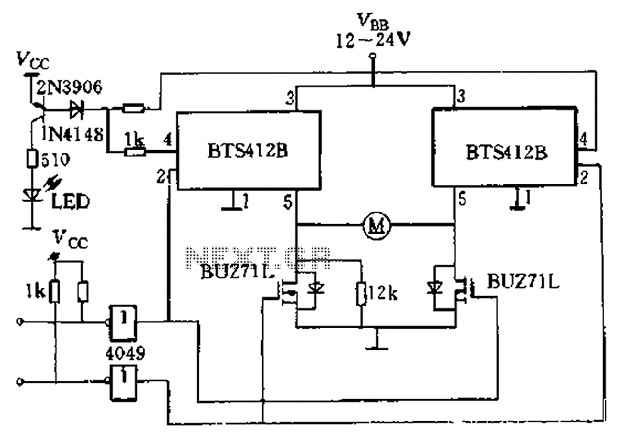
The BTS412B functions as two high-side power MOSFET switches, while two BU271L (50V, Zhang 1n) serve as low-side switches, forming a bi-directional H-bridge DC motor drive circuit. This configuration is designed for electrical automatic door systems, capable of handling...