
Af Drive Indicator Circuit

The circuit functions as a signal level indicator for audio power amplifiers, providing visual feedback on the amplifier's output performance. The primary components involved include two LEDs (D5 and D6) that serve as indicators for specific output conditions.
LED D5 lights up when the output level reaches -3 dB, which is a critical threshold indicating that the amplifier is nearing its maximum output capacity. This is essential for preventing distortion and maintaining audio quality, as exceeding this level can lead to clipping.
LED D6, on the other hand, activates when the output signal reaches the clipping point, signaling that the amplifier is unable to produce a higher output without distortion. Clipping occurs when the output signal is driven beyond the power supply limits, and continual operation in this region can damage the amplifier and connected speakers.
The circuit is designed to operate within a voltage range of 30 to 70 V, making it compatible with various audio amplifiers that utilize a symmetrical power supply configuration. This adaptability allows it to be integrated into different audio systems without requiring significant modifications.
To implement this circuit, a voltage divider or a similar method can be used to derive a portion of the amplifier's output voltage, which is then fed into a comparator or a similar circuit that determines when the output reaches the specified thresholds. The outputs of this circuit drive the LEDs, providing a clear and immediate visual indication of the amplifier's operating condition.
This design is beneficial for audio engineers and technicians who require real-time monitoring of amplifier performance, ensuring optimal operation and preventing potential damage to audio equipment. This circuit was used with an audio power amplifier to detect the point at which output is -3 dB from maximum, indicated by LED D5, and at clipping, shown by LED D6. The indicator can be used with any amplifier operating from a 30 to 70 V symmetrical supply.
Related Circuits
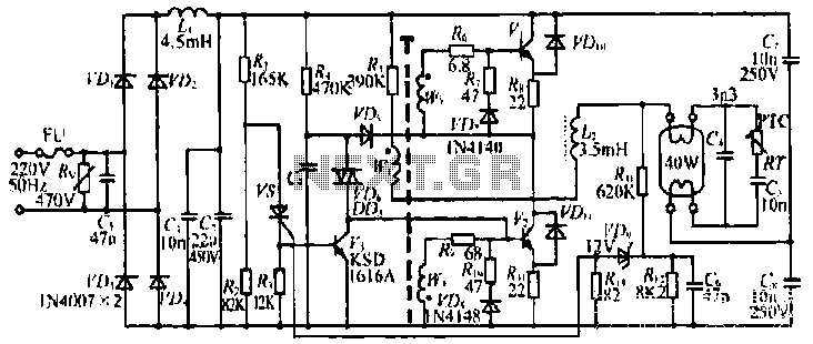
The figure illustrates the input from the varistor, which serves an overvoltage protection role. Components VDi and VD4 function as rectifiers, while L1 and C2 are utilized for filtering. The circuit comprises R, C9, and VD6, which are part...
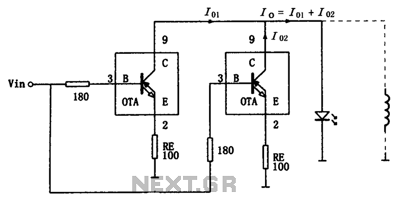
The high-speed parallel current drive circuit utilizes the OPA660 operational transconductance amplifier (OTA). An input signal, Vin, is connected to a 180-ohm resistor equivalent device at the base (pin 3) of the OPA660. The collector (pin 8) is directly...
Crystal Y1 generates a fundamental frequency clock signal of 14.31818 MHz. U31 is a Dual Voltage Controlled Oscillator (VCO) that produces a 14.31818 MHz clock signal, referred to as the color clock, at pin 10. The output frequency can...
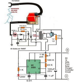
A fence charger or energizer is a device used to electrify a fence or boundary to protect the premises from human or animal intrusions. These boundaries are often located in large fields and parks, typically away from urban areas,...
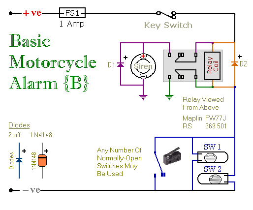
These are two easy-to-build relay-based alarms. They can be used to protect a motorcycle, but they have many additional applications. When using relays with 6-volt coils, they can safeguard a classic bike. Both alarms are compact, with completed boards...
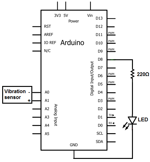
The sensors consist of a thin strip of piezoelectric material with a rivet at one end acting as a weight. When vibration occurs, the weight moves, stressing the piezo material, which generates a spike in voltage that can reach...