
Door Alarm

The door alarm circuit operates on the principle of detecting physical contact with the door handle. It utilizes a simple arrangement of resistors and a trimmer to form a voltage divider that triggers the beeping mechanism when the handle is touched.
The circuit includes the following components:
- R1: A 1MΩ, 1/4W resistor, which limits the current flowing through the circuit and helps in setting the sensitivity of the touch detection.
- R2: A 3.3KΩ resistor rated at either 1W or 2W, which works in conjunction with R1 to form a voltage divider that is sensitive to changes in resistance when the door handle is touched.
- R3: A 10KΩ, 1/2W trimmer resistor, which allows for fine-tuning of the circuit's sensitivity, enabling the user to adjust the beeping response based on the desired touch sensitivity.
The output of the circuit is connected to a beeping mechanism, such as a piezo buzzer or a small speaker, which will activate upon detecting the change in resistance caused by the touch on the door handle.
This door alarm circuit is suitable for home security applications, providing a simple yet effective means of alerting homeowners to potential intrusions. Proper placement on the door handle ensures maximum effectiveness, while the adjustable sensitivity allows for customization based on environmental factors.Door Alarm Hangs up on the door-handle Beeps when someone touches the door-handle from outside Free Circuit diagram: Parts List: R1 1M=1/4W ResistorR2=3K3 1 or 2W Resistor (See Notes)R3=10K 1/2W Trimmer.. 🔗 External reference
Related Circuits
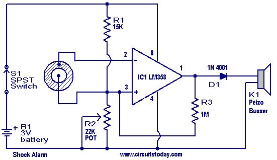
This is a simple shock-sensitive alarm circuit with numerous applications, ranging from home use to automobiles. The primary application of this circuit is as an anti-theft alarm for vehicles. A piezoelectric sensor is employed as the shock sensor and...

This is a two-zone alarm system featuring automatic exit, entry, and siren cut-off timers. It can be activated by standard normally-closed input devices, such as magnetic reed contacts, foil tape, and passive infrared sensors (PIRs). The circuit operates on...

A 2008 USA Nissan Pathfinder (VIN: 5N1AR18B28C628086) is experiencing issues with the power-assisted mechanism for closing the lift gate (trunk, rear door). The problem began approximately two months ago. The vehicle was taken to Willowdale Nissan in Thornhill, Ontario,...
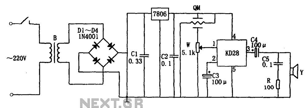
The system includes a gas-sensitive sensor element QM (type QM-N5), a buck rectifier, and regulator circuits, integrated circuits KD28, a speaker Y, and other components. The buck regulator circuit features a transformer rectifier and a bridge rectifier comprising diodes...
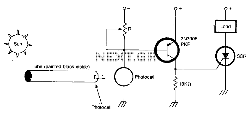
The circuit activates when light, specifically sunlight, strikes the photocell. A potentiometer, labeled R, adjusts the light level at which the alarm is triggered. Additionally, a painted tube, with a black interior, can be utilized on the photocell to...
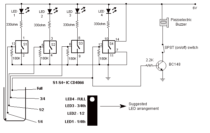
This circuit not only indicates the amount of water present in the overhead tank but also gives an alarm when the tank is full. The circuit uses the widely available CD4066, bilateral switch CMOS IC to indicate the water...