
Sun-powered alarm

The circuit utilizes a photocell (photoresistor) as the primary sensor to detect ambient light levels. When the intensity of sunlight reaches a predetermined threshold set by the potentiometer R, the circuit initiates an alarm signal. The photocell's resistance decreases with increasing light intensity, which in turn affects the voltage across the circuit.
The potentiometer R is a variable resistor that allows for fine-tuning of the light sensitivity. By adjusting this component, the user can define the specific light level at which the alarm will activate, ensuring that the circuit is responsive to the desired ambient conditions.
The inclusion of a painted tube, specifically designed with a black interior, serves to enhance the photocell's sensitivity to sunlight. This tube can help to concentrate the light entering the photocell, effectively increasing its response to sunlight while minimizing interference from surrounding light sources. The design of the tube is critical, as it must be positioned correctly to ensure optimal exposure to sunlight.
The overall circuit design may include additional components such as a transistor or relay to amplify the alarm signal, ensuring that it is loud enough to be heard in various environments. Power supply considerations should also be taken into account, with options for battery or solar power sources to enhance portability and efficiency.
In summary, this light-activated alarm circuit is a practical application of basic electronic principles, utilizing a photocell, potentiometer, and an optional focusing tube to create a responsive and adjustable alarm system.Circuit turns on when light (sunlight) strikes photocell. Potentiometer R sets light level at which the alarm sounds Painted tube (black on inside) may be used on photocell to aim at the sun.
Related Circuits
Construct a basic power failure alarm monitoring system utilizing an AC relay that activates a buzzer when the mains power supply is interrupted. The proposed power failure alarm monitoring system is designed to provide an audible alert during a loss...
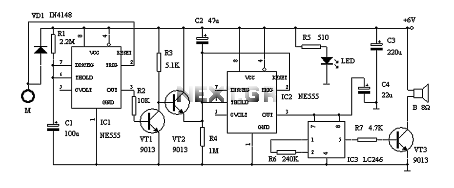
This circuit describes a door alarm system equipped with a time recognition feature. When the owner opens the door, it remains in a normal state for approximately 30 seconds without triggering the alarm. However, if the door is opened...
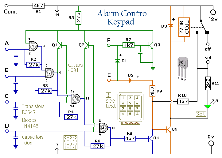
The Keypad must be the kind with a common terminal and a separate connection for each key. On a 12-key pad, look for 13 terminals. The matrix type with 7 terminals will NOT do. The Alarm is set by...
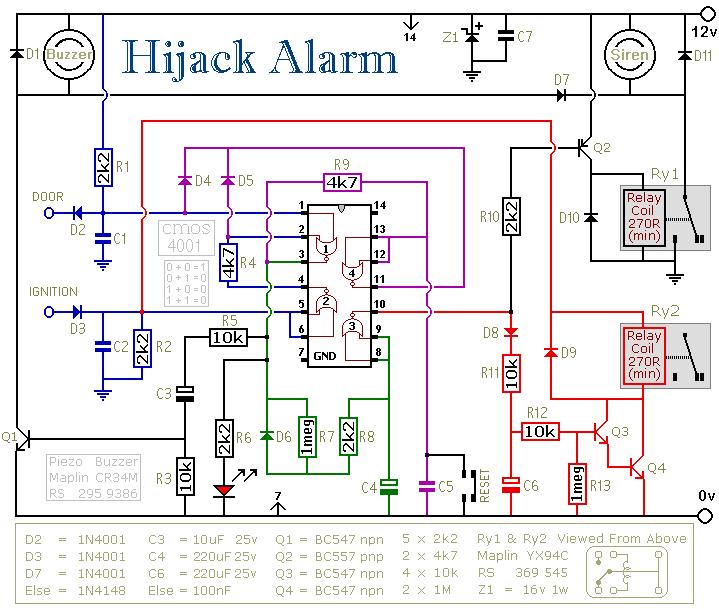
This circuit is designed primarily for the situation where a hijacker forces the driver from the vehicle. If a door is opened while the ignition is switched on, the circuit will trip. After a few minutes delay - when...
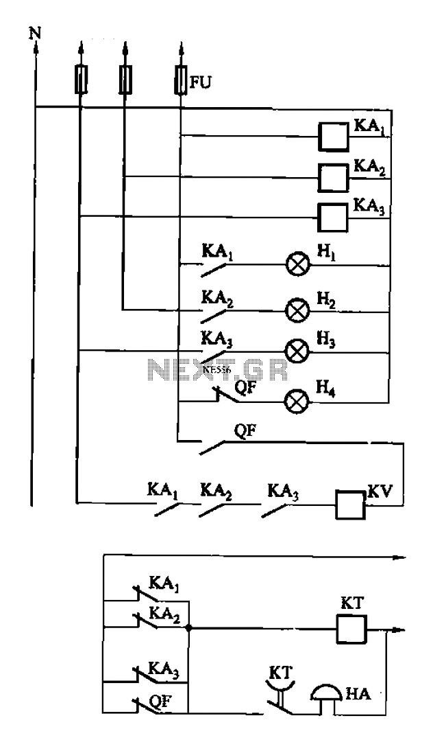
The circuit features intermediate relays KAi, KA2, and KA3, which are connected to the outlet end of the low-voltage circuit breakers. An alarm circuit is linked to a backup power supply or a battery power supply. This configuration serves...

Crime in general is still on the rise, and having a security alarm installed is no longer a prerequisite of the wealthy. Here is a simple and compact security solution. A compact security alarm system can be designed to enhance...