
AM circuit ring

The AM diode ring modulator circuit operates by utilizing four diodes configured in a circular arrangement, which enables effective mixing of the input signals. Each diode in the ring contributes to the modulation process, allowing for the combination of low-frequency audio signals with high-frequency carrier waves. The diodes are essential in shaping the output waveform, ensuring that the amplitude of the carrier signal is altered according to the amplitude of the modulating signal.
The specified diode model, 2AP9, is selected for its favorable characteristics in terms of forward voltage drop and switching speed, making it suitable for high-frequency applications. The resistive components, with values of 100Ω and 470Ω, serve to stabilize the circuit and optimize performance by providing necessary biasing and load conditions. These resistors help to ensure that the diodes operate within their optimal range, minimizing distortion and enhancing the fidelity of the output signal.
The output signal Qi produced by the circuit is a modulated waveform that retains the information of the original audio signal while being transmitted at a higher frequency. The design's simplicity is advantageous, as it reduces the complexity of the circuit and the potential for errors during assembly. Additionally, the low harmonic output contributes to a cleaner signal, which is crucial in communication systems where clarity is paramount.
This diode ring modulator circuit is often integrated into larger systems, such as radio transmission and reception modules, where compactness and efficiency are essential. Its balanced and symmetrical output characteristics make it an ideal candidate for integration into ICs, allowing for mass production and reliability in various electronic applications.AM diode ring circuit consists of four diodes to form a ring road, so called diode ring modulator circuit. AM diode ring circuits greater advantages. Due to the characteristics of the diode and discrete circuits, etc., often have to use resistive element correction circuit, the circuit shown
in actual annular AM diode VD are 2AP9. Other device parameters reference values: resistance; Ri = R2 = Ra = R4 -l OOtl, RRPI -Rr {PZ-470fl. Diode ring circuit low-frequency modulation signal amplitude and high frequency carrier signal by the high-frequency amplitude modulation circuit converting the signal output Qi. The amplitude modulation circuit is simple structure, less harmonic output, good balance and symmetry, often used in the form of an integrated circuit.
Related Circuits
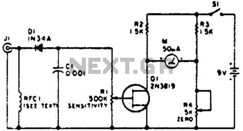
This circuit employs a FET as a DC amplifier within a bridge configuration. Resistor R4 is adjusted for meter nulling with switch J1 short-circuited. Any surplus 50-mA meter can be utilized in this circuit. RFC1 represents a suitable RF...
Bidirectional control is implemented for a motor to increase its operational degree. The motor can rotate in either direction with a current of 1A. A variable duty cycle multivibrator is utilized to achieve the construction and control of the...
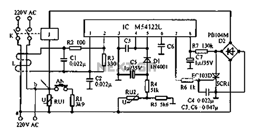
The multifunction leakage protection switch utilizes the Nissan ASIC M54122L. It is designed to serve as a multi-function leakage protection switch. In the event of leakage or electric shock, the magnetic field generated through the inductor line and neutral...
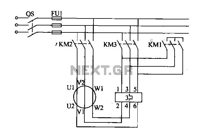
Traditional control methods for fan power equipment involve manual or relay control, which often leads to issues of poor reliability and flexibility. For instance, when the motor capacity is large, the startup process can be prolonged, resulting in high...
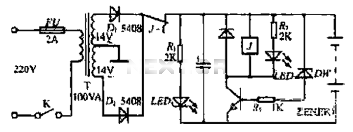
The refrigerator turned on, causing the lights to brighten. Initially, it seemed like an illusion, but after observing multiple cycles, the phenomenon persisted. When the microwave was activated, the lights dimmed. The refrigerator's operation appeared to influence the brightness...
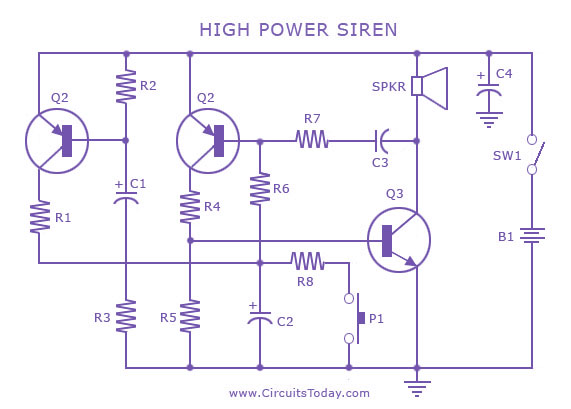
A siren circuit diagram that generates a strong, high-power siren or alarm sound using complementary transistor pairs BC 557 and BC 337, arranged as an oscillator. The described siren circuit employs a pair of complementary transistors, BC 557 (a PNP...