
Door light emitting logic circuit with CD4069

The logic pen operates by applying a test voltage to the point of interest in the circuit. It can effectively determine whether the logic level is high, low, or floating based on the voltage present at the test point. When the probe is connected to a high logic state, the LED will illuminate, typically in a specific color such as green or yellow, indicating a logic "1". Conversely, when the probe detects a low logic state, the LED may light up in a different color, such as red, to signify a logic "0". In cases where the circuit point is floating or in a high-impedance state, the LED remains off, signaling that there is no definitive logic level present.
The inclusion of a sounder enhances the functionality of the logic pen by providing an audible indication of the logic state, which can be particularly useful in noisy environments or when the user is unable to visually monitor the LED display. The use of the CD4069 hex inverter within the logic pen circuit allows for the amplification and inversion of input signals, making it easier to detect and interpret the logic states accurately.
Overall, the logic pen is an essential tool for electronics engineers and technicians, aiding in troubleshooting and verifying the operation of digital circuits efficiently. Its simple design, combined with the intuitive feedback mechanisms of LED indicators and sound alerts, makes it an invaluable asset for anyone working with digital electronics.Logic pen also known as logic detection probe, it is a common tool in the digital circuit detection logic state of each point. Digital circuit logic state is generally divided into three types: namely, a high level "l", the low level "0"
and "high impedance" (floating). The logic state of the test results by the light emitting diode display, can also be used to prompt the sounder, but also with a digital light-emitting diode displays. Shown for the use hex inverter CD4069 light emitting diode logic detecting pen.
Related Circuits
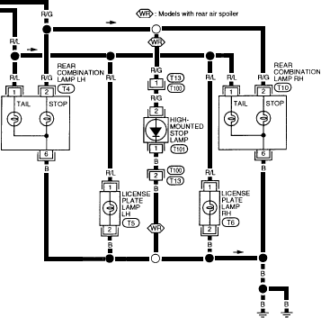
1995 Nissan Altima Brake and Tail Light Wiring Diagram. The wiring diagram for the brake and tail lights of the 1995 Nissan Altima provides a visual representation of the electrical connections and components involved in the lighting system. This diagram...
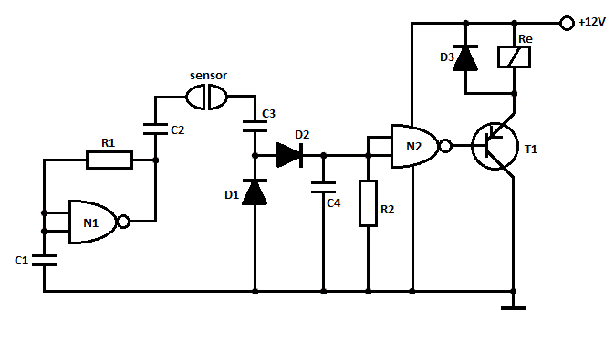
This is a straightforward liquid detector that utilizes a relay to activate an evacuation mechanism. It can be employed for water or any liquid that conducts electricity. Any PNP transistor capable of handling the relay current can be used....

The internal structure of the DTL inverter circuit (M5936P) is composed of inputs with diodes and transistors for signal processing, powered by a +5V supply. When the input terminal A is at a high level (digital 1), diode VDI...
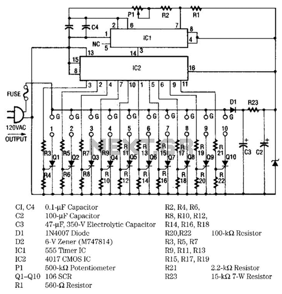
The light sequencer employs two integrated circuits (ICs) and ten silicon-controlled rectifiers (SCRs) to create an alternating current (AC) sequencer. The first IC, a 555 timer, is configured as an astable multivibrator to generate clock pulses for the second...

This lighting solution offers over 90% energy savings compared to incandescent or halogen bulbs, with a lifespan exceeding 50,000 hours. It operates without flickering, making it suitable for human eyes, and produces no RF interference or UV radiation. The...
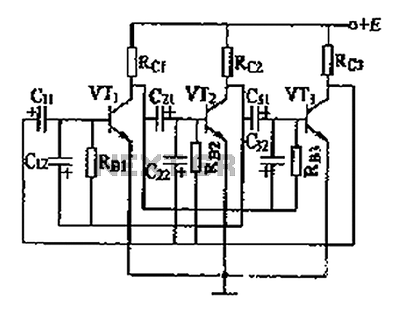
The three astable circuit is illustrated, demonstrating that each level of the transistor's base is connected by a capacitor between the two levels, ensuring tight coupling. Additionally, each base electrode is biased through a resistor (Rb) connected to the...