
Three astable circuit diagram

The astable multivibrator circuit consists of three transistors arranged in a cascading configuration, each serving as a switch that alternates between on and off states. The coupling capacitors between the transistor bases facilitate the timing and synchronization of the switching operation. When one transistor is driven into saturation, it allows current to flow through the collector-emitter junction, effectively turning on the next transistor in the sequence.
The biasing resistors (Rb) connected to the base of each transistor ensure that they operate within their active regions during the switching process. This arrangement prevents multiple transistors from being saturated simultaneously, thereby maintaining a stable oscillation pattern. The timing of the transitions is determined by the values of the resistors and capacitors used in the circuit.
In practical applications, this astable multivibrator can be utilized for generating square wave signals, timing applications, or as a clock pulse generator in digital circuits. The frequency of oscillation can be adjusted by modifying the capacitor values or the resistor values, allowing for versatile operation in various electronic systems. Overall, the design ensures reliable performance and efficient switching behavior, making it suitable for a wide range of electronic applications. As shown for the three astable circuit. From this circuit can be seen, each level of the base of the transistor by a capacitor connected between the two levels are tightly coup led by a capacitor and the collector to other levels, and at all levels of the base electrode bias resistor Rb and stage connected to the collector. This ensures that at the same time only one tube is saturated, while the other levels to the OFF state, a saturated tube front to the rear and then click Convert.
Related Circuits
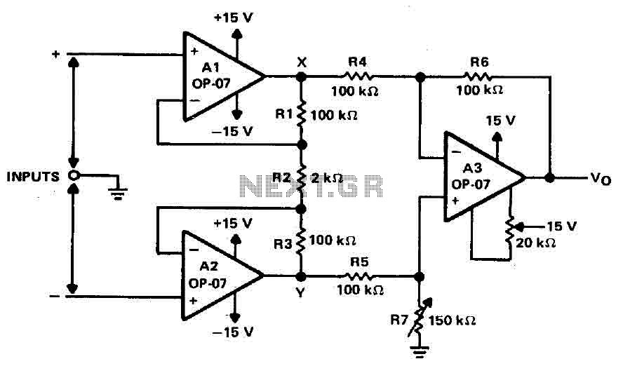
Operational amplifiers A1 and A2 are connected in a non-inverting configuration to form amplifier A3. The operational amplifier A3 can be classified as a subtractor circuit that converts the differential signal between the floating points X and Y into...
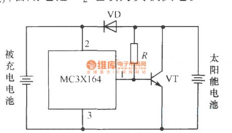
The following circuit illustrates a current-limited solar battery charger circuit diagram. This lead-acid or Ni-Cd battery charger circuit diagram utilizes solar energy to charge a 6-volt, 4.5 Ah rechargeable battery for various applications. It represents a straightforward solar battery...
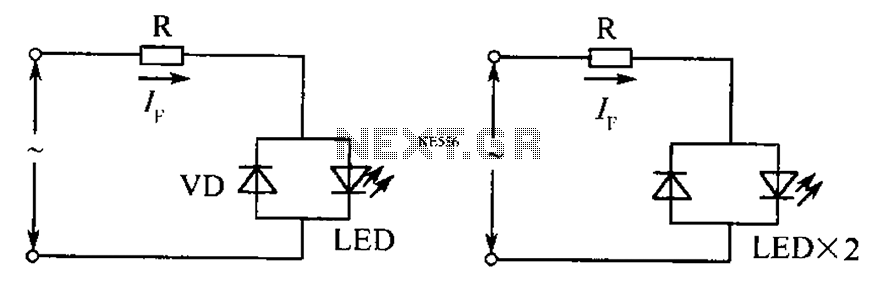
The circuit operates effectively even when the polarity of the voltage or the power supply is reversed. It functions with DC drives similar to AC drives, utilizing a current limiting resistor R. The value of this resistor is determined...
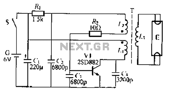
The circuit described is a battery-powered fluorescent lamp system designed for temporary emergency lighting during power outages. It utilizes a transistor (V7) and a boosting transformer (T) along with an inductive feedback oscillator to generate a high-voltage output. When...
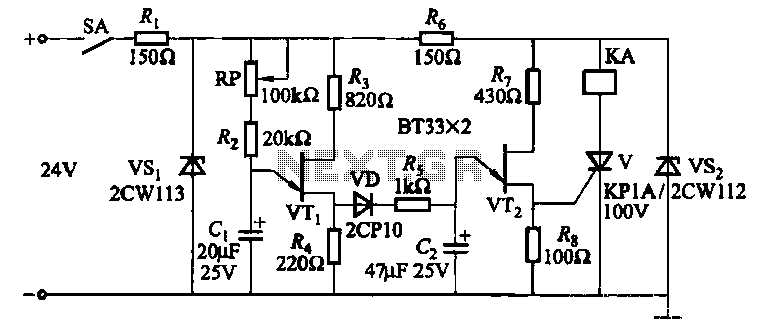
This circuit consists of three single-junction transistor time relay circuits utilizing a pulse charging mechanism, allowing for extended delay times of up to several minutes. The first stage delay circuit incorporates unijunction transistors (VTi) and other components, where capacitor...
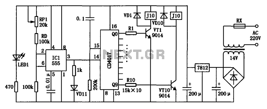
Modern exhibitions utilize extensive sound, light, and electrical technologies for advertising, promotion, and propaganda. This involves various electrical diagrams and control models. Commonly used is an automatic program circuit with pre-recorded commentary, which requires synchronization of two mating times....