
Doorbell MemoryCircuit

An electronic doorbell memory system is designed to capture and store the identity of visitors who press the doorbell when the homeowner is unavailable. This system typically consists of a doorbell button, a microcontroller, a memory module, and a display unit. When the doorbell button is pressed, the microcontroller activates and records the time and date of the event. The system can also include a camera module that captures an image of the visitor, which is then stored in the memory module alongside the timestamp.
The memory module is crucial as it retains the information even when the power is turned off. It can be a non-volatile memory type such as EEPROM (Electrically Erasable Programmable Read-Only Memory) or flash memory. The display unit can be an LCD or LED screen that shows the recorded information, allowing the homeowner to view who visited while they were away.
In addition to the basic functionality, more advanced systems may integrate features such as remote notifications sent to the homeowner's smartphone or email when the doorbell is pressed, allowing for real-time awareness of visitors. Some systems may also include a voice recording feature to leave messages for the visitor, enhancing communication even in the homeowner's absence.
Overall, an electronic doorbell memory system enhances security and convenience, ensuring that homeowners do not miss important visitors while they are temporarily away from the entrance.If you re expecting an important visitor but you just have to step out for a moment, an electronic doorbell memory can come in handy so you can see whethe.. 🔗 External reference
Related Circuits
If expecting an important visitor but needing to step out for a moment, an electronic doorbell memory can be useful to check if someone rang while away. It may not indicate if the expected visitor arrived, but a quick...
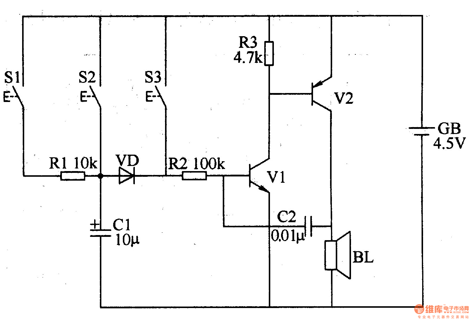
The three-tone electronic doorbell circuit includes buttons S1-S3, transistors V1 and V2, a speaker BL, resistors R1-R3, capacitors C1 and C2, a diode VD, and a battery GB, as illustrated in Figure 3-109. Resistors R1-R3 are 1/4W carbon film...
All components are arranged as depicted in the sequence below. Current will flow from the source voltage to the switch. When the switch is closed, current will flow through the diode, which acts as a closed switch due to...
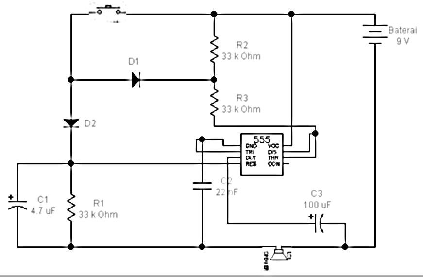
This simple and cost-effective ding-dong electronic doorbell circuit is based on IC 8021-2. The IC has an integrated circuitry that generates a ding-dong sound each time its pin 3 is pulled low. The sound is stored in the IC...
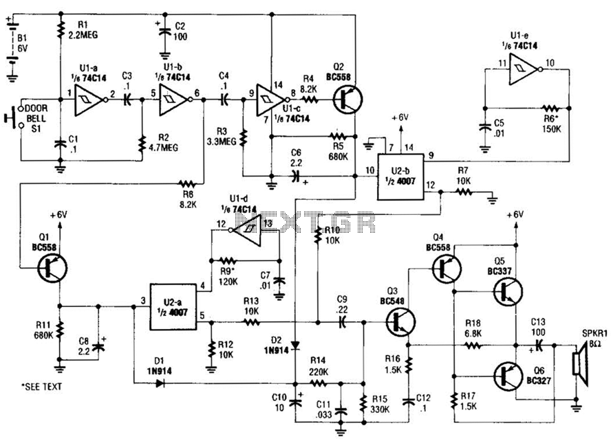
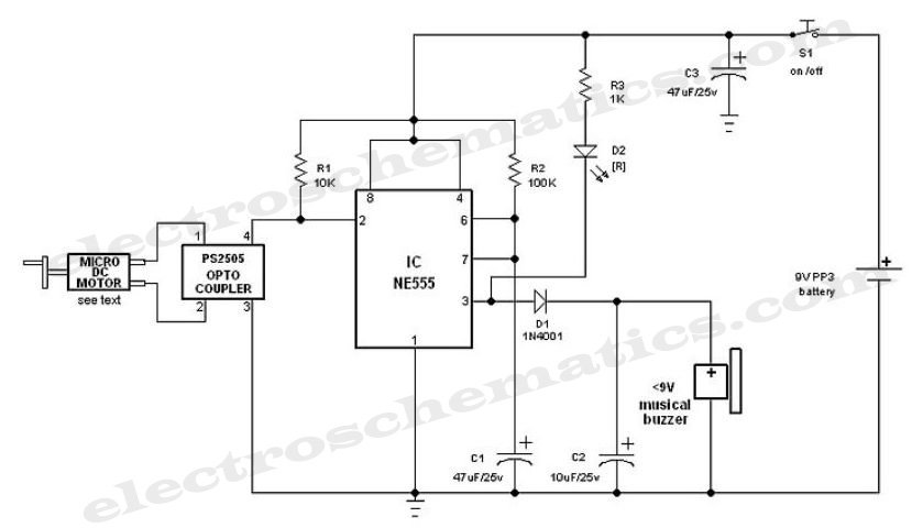
When the doorbell switch is pressed, two monostable stages are sequentially activated, applying bias to a pair of voltage-controlled resistor stages. These stages modulate the outputs from a pair of tone generators. The resulting signals are then fed to...
Understanding the pins of an integrated circuit (IC) is crucial for circuit construction. Pin 1 (GND) is connected to ground, representing a low voltage level (0 V). Pin 2 (TRIG) is used to trigger the operation of the circuit....