
Electronic Doorbell Circuit

The described circuit functions as a doorbell chime system, employing two monostable multivibrators that operate in a sequential manner. Upon activation of the doorbell switch, the first monostable stage is triggered, producing a short pulse that initiates the operation of the second stage after a predetermined delay. This sequence creates a distinct pattern of activation that is essential for generating a unique audio signal.
The voltage-controlled resistors (VCRs) play a critical role in shaping the audio output. By adjusting the resistance based on the control voltage received from the monostable stages, the VCRs allow for nuanced modulation of the tone generators' outputs. The tone generators are typically configured to produce specific frequencies that correspond to the desired chime sound.
The audio signals produced by the tone generators are then routed to an audio amplifier, which boosts the signal strength to drive a speaker effectively. The amplifier ensures that the sound produced is loud enough to be heard clearly at a distance. The final output is delivered through the speaker, providing an audible indication of someone at the door.
This schematic illustrates a straightforward yet effective approach to designing a doorbell chime system, integrating sequential logic with audio modulation techniques to create a pleasant and functional alerting mechanism. When the doorbell switch is pressed, the two monostable stages are activated in sequence, applying bias to a pair of voltage-controlled resistor stages. These then modulate the outputs from a pair of tone generators. The resulting signals are fed to an audio amplifier, then to the speaker.
Related Circuits
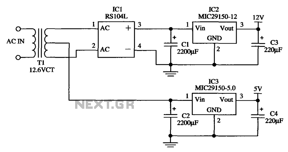
The low-cost dual output voltage regulator circuit is composed of two Micrel company regulators, the MIC29150-12 and the MIC29150-5.0. The dual output voltage regulator circuit utilizes the MIC29150 series from Micrel, which are low-dropout (LDO) voltage regulators designed for various...

This is a simple smoke alarm circuit using a timer IC, the NE555. The circuit operates by illuminating a Light Dependent Resistor (LDR) with a lamp. When smoke obscures the light from the lamp, the resistance of the LDR...

The clock pulses from the 555 astable circuit are sent into the 4017 decade counter. Each output becomes high in turn as the clock pulses are received. Appropriate outputs are combined with diodes to supply the amber and green...

None of this triggering circuitry is exactly what is desired, but it will provide a starting point in the right direction. The triggering circuitry mentioned serves as a foundational element for various electronic applications, particularly in the realm of signal...

The following circuit illustrates the Bedside Lamp Timer Circuit utilizing the CD4060 integrated circuit (IC). It operates for 30 minutes, with a blinking LED indicating the last 6 minutes of operation. The Bedside Lamp Timer Circuit is designed to provide...
When the switch SI is pressed, the silicon-controlled rectifier (SCR) is activated, connecting LED1 and resistor R1 across the telephone line. This action causes the line voltage to drop to approximately 20 volts, which maintains the connection to the...