
Driving a servo with MOSFET

To construct a battery-powered device with a servo motor and effective power management, a comprehensive understanding of MOSFET operation and circuit design is essential. The circuit should include a battery source, a servo motor, and a MOSFET that will act as a switch to control the servo's power supply.
The circuit design can start with an N-channel MOSFET for low-side switching. This configuration typically provides better efficiency and thermal performance. The MOSFET should be rated for a voltage higher than the battery voltage and for a current that exceeds the servo's stall current. A common choice for such applications is the IRF520 or similar devices.
To control the MOSFET, a microcontroller or a simple switch can be used. If a microcontroller is employed, a GPIO pin can be connected to the gate of the MOSFET through a resistor (typically 10kΩ) to limit the current. A pull-down resistor (around 10kΩ) should also be connected from the gate to ground to ensure that the MOSFET remains off when not driven by the microcontroller.
For the servo motor, the power supply should be connected to the drain of the MOSFET, while the source is connected to ground. The servo's control signal can be connected directly to the microcontroller's PWM output pin, allowing for precise control over the servo's position.
In the case of using a P-channel MOSFET for high-side switching, the circuit configuration will differ slightly. The source of the P-channel MOSFET should be connected to the positive voltage supply, while the drain connects to the servo motor. The gate of the P-channel MOSFET should be driven low to turn on the device, which can be achieved through a microcontroller output, with a pull-up resistor connected to the positive supply.
In either case, it is crucial to ensure that the MOSFET is adequately rated for the application and that appropriate heat dissipation measures are in place, such as using a heatsink if necessary. Additionally, including bypass capacitors near the power supply pins of the servo can help stabilize the voltage and improve performance.
This design approach provides a robust solution for controlling a servo motor in a battery-powered application while conserving battery life through effective switching techniques.Build a small battery powered device containing a servo. I would like to be able to turn off the servo to save battery life. I have read previously that MOSFETs can be used to do this, but I am having trouble finding example circuits that are detailed enough (missing resistor values with no way to calculate them) and to be honest Iam not too sure what sort of circuit I am looking for (I have never used any FETs before). Can someone please give me a nudge in the right direction If you want practical guidance, including part selection, look at some of the speed control projects for R/C systems which have been published - preferably a recent one. A FET that can run the drive motor should have little trouble with a servo. One thing to think about is if you could get away with using an N-channel device to switch the low side as those are fundamentally better than the P-channel devices.
However, the brushless motor controllers that are all over the place today use both, so you could pick a P-channel device and drive circuit from there for high side switching. Chris Stratton Aug 1 `12 at 14:56 🔗 External reference
Related Circuits
Circuit to control RC servos using 0-10V control voltage This circuit is designed to control RC servos by utilizing a control voltage range of 0 to 10 volts. The operation of the circuit is based on the principle of converting...
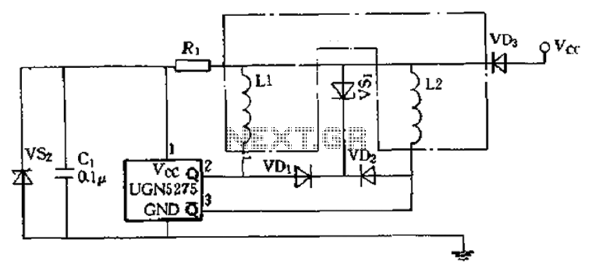
The circuit features almost open collector outputs with a withstand voltage of 60V and a continuous conduction current of 0.3A. The typical voltage drop is 0.4V, with a peak current capability of 9A. It can directly drive two windings...
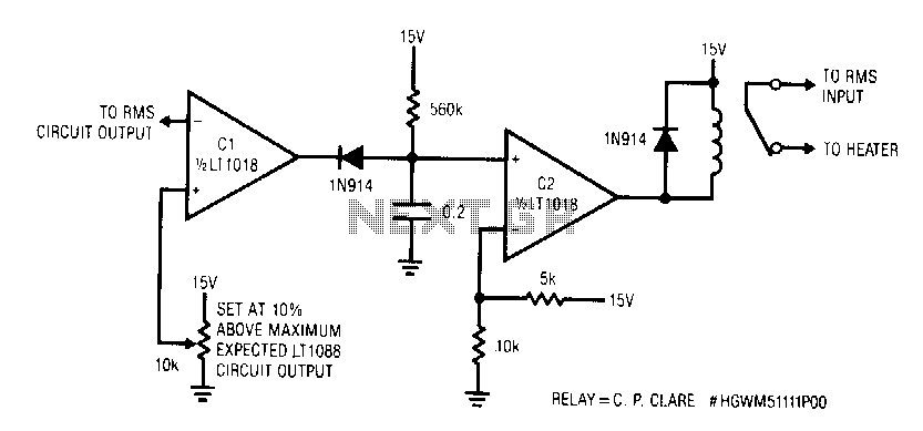
This circuit responds quickly enough to prevent damage from most overloads. Capacitor C1's input is connected to the output of the LT1088 servo circuit. If the LT1088 circuit's output exceeds the threshold at C1's other input, C1 trips, discharging...

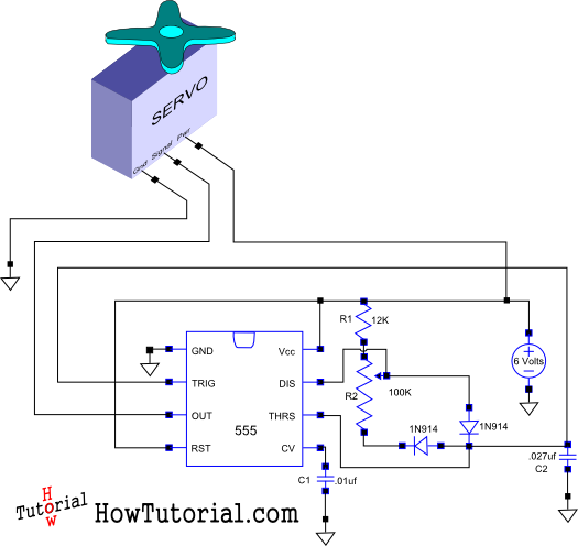
This is a simple basic design of a servo motor controller with a pulse generator. It utilizes the CMOS IC 7555 in astable mode to generate pulses for driving the motor. The servo motor controller circuit employs the CMOS IC...
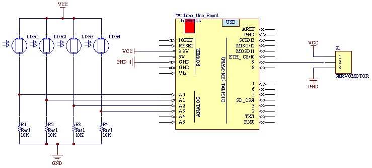
The movement of the servo is determined by the output values of the photoresistors. The impedance of these sensors changes with the amount of light incident upon them. The servo's position shifts towards the sensor that detects less light....
This document outlines the design of a simple circuit that enables control of a servo motor and allows for testing its functionality. The circuit for controlling a servo motor typically consists of a microcontroller, a power supply, and the servo...