
Servo Motor Controller Circuit

The servo motor controller circuit employs the CMOS IC 7555 configured in astable mode to produce a continuous square wave output. This output serves as a pulse signal that is crucial for controlling the position and movement of the servo motor. The frequency and duty cycle of the generated pulses can be adjusted by changing the resistor and capacitor values connected to the 7555 IC.
In astable mode, the 7555 operates without any stable state, constantly switching between high and low outputs. The timing components, typically a combination of resistors (R1, R2) and a capacitor (C), define the frequency (f) of the output waveform. The frequency can be calculated using the formula:
\[ f = \frac{1.44}{(R1 + 2R2) \cdot C} \]
The duty cycle, which determines the proportion of time the output is high versus low, is influenced by the resistor values, allowing for fine-tuning of the pulse width. This is critical for matching the requirements of the specific servo motor being controlled.
The output of the 7555 is connected to the control input of the servo motor, which interprets the pulse width to adjust its position accordingly. Additionally, the circuit may include a power supply section to provide the necessary voltage levels for the IC and the servo motor, ensuring reliable operation.
Overall, this simple servo motor controller design is effective for applications requiring precise control of motor position, such as in robotics, automation systems, and remote-controlled devices.This is the simple basic design of servo motor controller with pulse generator. It uses the CMOS IC 7555 in the Astable mode to generate pulses to drive th.. 🔗 External reference
Related Circuits
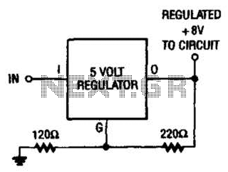
If locating an 8-V regulator proves difficult, a 5-V unit can serve as a replacement by connecting the regulator as illustrated here. In electronic circuits, voltage regulators are essential components that maintain a constant output voltage regardless of variations in...
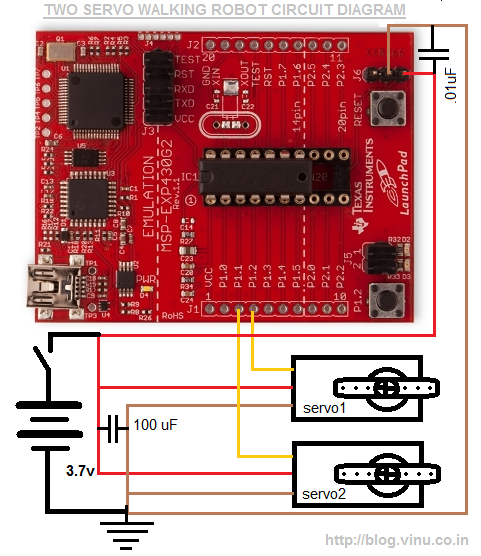
Two small servo motors were purchased last month, leading to the idea of creating a four-legged walker using these two servos. A friend suggested this project and shared a YouTube video demonstrating a similar concept. The design was developed...

The system consists of a MAX1463 precision pressure detection circuit block diagram. The output voltage from the bridge pressure sensor is connected to the MAX1463 inputs IN1+ and IN1-. Controlled by a CPU, the pressure signal undergoes nonlinear calibration...

The following circuit illustrates a Frequency Voltage Converter Circuit. This circuit is based on the LM331 IC and operates with a supply voltage of 15V DC. The Frequency Voltage Converter Circuit utilizes the LM331 integrated circuit, which is designed for...

The ramp voltage from the low-frequency oscillator IC1 modulates IC2, thereby producing a rising and falling tone similar to the wail of police cars. The described circuit utilizes a low-frequency oscillator (IC1) to generate a ramp voltage. This ramp voltage...
This is an LM338-based power supply that is uncomplicated and easy to construct. It has been in use for an extended period without any issues. The circuit lacks a current adjustment feature, which has been addressed by incorporating an...