
Dual Axis Stepper Motor Controller

The circuit design for the dual-axis stepper motor controller is based on the integration of various electronic components that work together to achieve precise control of the motors. The SAA1042 stepper motor controller IC is central to this design, enabling high current output necessary for the operation of stepper motors in both the polar and declination axes. The inclusion of a crystal oscillator ensures stable timing for the motor operations, while the programmable divider allows for flexible adjustment of the motor stepping rate, accommodating different astrophotography needs.
The multiplexers play a crucial role in selecting the appropriate clock frequency for the motors, ensuring that the system can adapt to various operational requirements. The use of NPN transistors for level shifting is an important design consideration, as it allows the integration of 5V logic with the requirements of the SAA1042, which operates at different voltage levels. The choice of a linear voltage regulator for powering the CMOS components is also significant, as it provides a stable 5V supply while maintaining the necessary input voltage levels.
In terms of connectivity, the four input/output ports facilitate interaction with external devices, such as handpads for manual control and programmable divider controls for user-defined settings. This modular approach enhances the versatility of the circuit, allowing it to be tailored to specific applications, whether for astrophotography or visual telescope use.
Overall, this dual-axis stepper motor controller design exemplifies a comprehensive approach to electronic circuit design, integrating various components and functionalities to deliver a robust solution for controlling stepper motors in an equatorial mount setting.This page describes a dual axis stepper motor controller design and printed circuit board for an equatorial mount. Much thanks goes to Bill Prewitt for his help in the design of this web page. Download encapsulated postscript file of the artwork. This file contains the artwork for both sides of the printed circuit board artwork. zip [31K]. Upon dec ompression you will find both mirrored and unmirrored versions of the top and bottom artwork. The circuit described on this page was designed to drive the stepper motors on an equatorial mount for the purpose of astrophotography. I have designed in several features which are needed for photography but which are unnecessary for the person wishing a motorized drive for a visual-only telescope where a single-axis, constantrate drive would prove adequate.
The main complications in the circuit come from having two driven motors and from the necessity of having slow motion control on both axes. However, even for visual work, I have found that this system, especially the fast slewing function, makes the telescope more enjoyable to use.
This project is not easy if you don`t have some electronics experience. For that reason, I have included detailed schematics of the circuit. This may help you understand what`s supposed to happen in the circuit in case you get into trouble. Access to an oscilliscope may be necessary for troubleshooting. There are several ways to fabricate this circuit. I have included artwork for a homemade double-sided PC board and some instructions that you may find useful. On the other hand, most of the circuitry could be interconnected using wire wrapping techniques. I have not tried this method. If you do, be careful about the thermal dissipation of the SAA1042 stepper motor IC`s. The circuit described herein uses the Motorola SAA1042 stepper motor controller IC to provide the high current signals to the stepper motors.
There is one SAA1042 for the polar axis motor and one for the declination axis motor. The clocks for the SAA1042 are derived from a 4 MHz crystal oscillator which is divided down by a programmable divider comprised of four 74HC160 counter IC`s and a 74HC02 Nor gate. The programmable divider allows the user to set the stepping rate for sidereal motion over a wide range.
A further set of dividers is used to create a number of clock frequencies that are switched into the SAA1042`s to allow motion control for both axes. On the schematics, these clock frequencies are labeled 0. 5x, 2x, etc. and denote the frequency with respect to sidereal rate (1x). Two multiplexers (74HC151) are used to select the clock frequency for motion control. Finally, four NPN transistors and twelve resistors are used to level shift the clock and direction inputs to the SAA1042 from 5V CMOS logic to the logic levels needed by the SAA1042.
A 5V regulator (78L05) is used to make the power supply voltage for the CMOS devices. There are four input/output ports for this circuit: 1) Power and Ground; 2) Handpad Interface; 3) Programmable Divider Control; and 4) Stepper Motor Interface. Each of these is discussed in the following. Power and ground. The input power to the circuit directly drives the stepper motors, so, if you plan on using batteries to power the circuit then the rated voltage of the motors should be a convenient voltage which can be derived from the batteries.
In most instances, 12 volts should be used. A linear voltage regulator (78L05) is used to provide the CMOS circuits with 5V. This regulator will drop-out at an input voltage of 7V or lower. For this reason, the input voltage should always be maintained above 7V. The stepper motor control IC comes in two flavors: The SAA1042 is intended for 6V to 12V steppers and the SAA1042A is intended for use with 15V to 24V steppers. So, if you want to use a higher-voltage stepper, order the SAA1042A. In some applications, a lot of current may be used to drive the steppe 🔗 External reference
Related Circuits
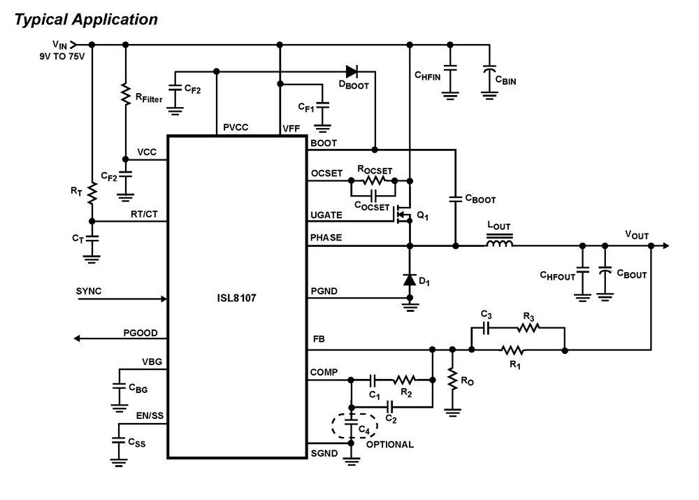
The ISL8107 is a single-phase, non-synchronous buck controller equipped with an integrated high-side MOSFET driver. It operates within an input voltage range of 9V to 75V. The internal reference voltage is 1.192V with a tolerance of ±1% across the...
This circuit generates a double tone sound similar to that of a police siren and a single tone sound reminiscent of an old ambulance. It is typically installed in battery-powered vehicles such as cars and motorcycles. The circuit utilizes a...
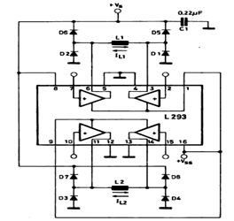
This circuit illustrates a basic configuration for driving a bipolar stepper motor using either an L293 or an L298N driver. It demonstrates that a single device can control a two-phase bipolar stepper motor. The circuit employs either the L293 or...
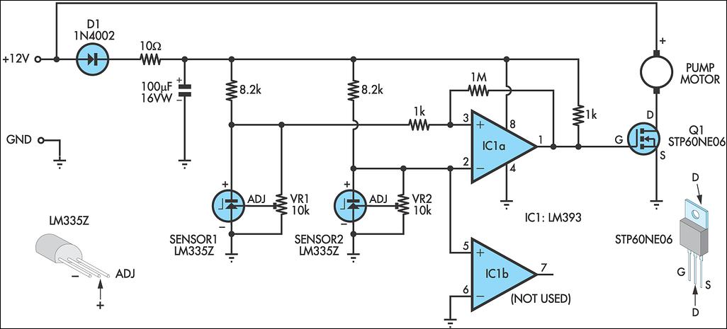
A solar water heating pump controller is an essential component in most solar water heating systems, whether DIY or commercially produced. Its primary function is to activate the pump when the fluid in the solar panel is at a...
Bridges enable robots to control high-current motors by connecting the low-current logic circuitry of the robot's brain to the high current required by the motors. Many bridges utilize the common "H" arrangement of control circuitry, typically involving power transistors,...
This circuit was built to stabilize a radio frequency VFO (Variable Frequency Oscillator) for ham radio applications. The circuit has also been used to lower the drift of a Ramsey FM10a micropower FM transmitter. More: The 7805 voltage regulator...